Picture |
Object
name
#NORAD |
Description |
Launch
Date |
Weight |
|
OSCAR
0
OSCAR Zero
Moon
#00001 |
Radio amateurs use the
Moon as a passive repeater (reflector) and thus call
him sometimes OSCAR Zero. The first radio amateurs who
successfully received signals bounced off the moon were
Ross Bateman (W4AO) and Bill Smith (W3GKP). They received
the echo on 144 MHz in 1953. |
Jul
20th 1969 |
735
*1020
kg |
 Enclosed
Moon Bounce SSB transmissions were done from KP4BPZ
in Arecibo, Puerto Rico, using the 1000 foot diameter
radio telescope dish. KP4BPZ was running about 500 watts
on 432 MHz. This recording was made by Roy W0SL in Florissant,
Missouri on July 3rd, 1965. Enclosed
Moon Bounce SSB transmissions were done from KP4BPZ
in Arecibo, Puerto Rico, using the 1000 foot diameter
radio telescope dish. KP4BPZ was running about 500 watts
on 432 MHz. This recording was made by Roy W0SL in Florissant,
Missouri on July 3rd, 1965.
|
The moon
can be used as a reflector also at Microwave frequencies
as demonstrated in the next few recordings kindly provided
by Michael OH2AUE. This recording is from the first
Finish 10 GHz EME QSO (in CW) with WA7CJO. OH2AUE built
the equipment and the 6.4 meter dish from OH2AXH was
used. |
The first
Finnish 5.6 GHz EME QSO (in SSB) took place in 1995.
You can hear the voice of OH2AXH as well as the echo
of the reflected signal loud and clear. TRX from OH2AUE
and 6.4m dish from OH2AXH. Recorded in 1998 by Michael
OH2AUE. |
First
Finish 3.4 GHz EME QSO (in CW) with WB5LUA. TRX from
OH2AUE and dish from OH2AXH. Recorded on January 5th
1998 by Michael OH2AUE. |
During
the first World Moon Bounce Day on June 27th
2009 Astronaut William Anders, who was part of the Apollo
8 crew, gave an interview to Joe K5SO which was bounced
off the moon. William Andres voice was transmitted by
W6SRI, the club station of SRI Amateur Radio Society.
Recording kindly provided by Pat AA6EG. |
|
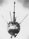
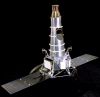
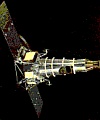
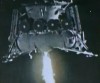
Pioneer
1
Pioneer I
Able 2
#00110
(1958-007A) |
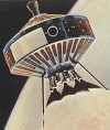
Pioneer 1, the second
and most successful of three project Able space probes
and the first spacecraft launched by the newly formed
NASA, was intended to study the ionizing radiation,
cosmic rays, magnetic fields, and micro-meteorites in
the vicinity of the Earth and in lunar orbit. Due to
a launch vehicle malfunction, the spacecraft attained
only a ballistic trajectory and never reached the Moon.
The spacecraft did return some data on the near-Earth
space environment and ended its transmission when it
reentered the Earth's atmosphere after 43 hours of flight
on October 13th 1958 at 03:46
UTC over the South Pacific Ocean.
Radio transmission
was at on 108.06 MHz through an electric dipole antenna
for telemetry and doppler information at 300 mW and
a magnetic dipole antenna for the television system
at 50 W. Ground commands were received through the electric
dipole antenna at 115 MHz. |
Oct
11th 1958 |
34.2
kg |
This
recording of the launch of Pioneer 1 is from vinyl no.
5 which was included in the Italian Enciclopaedia Luomo
e lo spazio (The man and the space) issued 1965 by Fratelli
Fabbri. Digitized and kindly provided by Federico Manzini. |
This
recording from Dick W4PUJ/SK is most likely from Pioneer
1 but it could have been also from Pioneer 3. |
|
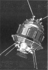
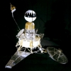
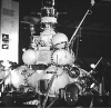
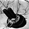
Lunik
I
Luna 1
Mechta
#00112
(1959-012A) |
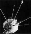
Luna 1 was the first
of a series of Soviet automatic interplanetary stations
successfully launched in the direction of the Moon.
It actually landed on the Moon.
|
Jan
2nd 1959 |
361
kg |
This recording
of a Lunik probe was kindly provided by Dick W4PUJ/SK.
It is possibly from Lunik I but we are not sure. It
could be also based on transmissions of Lunik II or
Lunik III. |
|
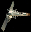
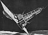
Pioneer
3
Pioneer III
#00111
(1958-008A) |
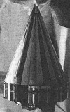
Pioneer 3 was a spin
stabilized spacecraft launched by the U.S. Army Ballistic
Missile agency in conjunction with NASA. The spacecraft
failed to go past the Moon and into a heliocentric orbit
as planned. Instead it reached an altitude of 102360
km before falling back and re-entering Earth's atmosphere.
It finally burned up over Africa on December 7th
at approximately 19:51 UTC.
The revised spacecraft
objectives were to measure radiation in the outer Van
Allen belt area using Geiger-Mueller tubes and to test
the trigger mechanism for a lunar photographic experiment.
A transmitter with a mass of 0.5 kg delivered a phase-modulated
signal at a frequency of 960.05 MHz. The total effective
radiated power was 0.18 W. |
Dec
6th 1958 |
5.9
kg |
This
recording from Dick W4PUJ/SK is most likely not from
Pioneer 3 but most likely from Pioneer 1. |

|
Pioneer
4
Pioneer IV
#00113
(1959-013A) |
Pioneer
4 was a spin stabilized spacecraft launched on a lunar
fly-by trajectory and into a heliocentric orbit making
it the first US probe to escape from the Earth's gravity.
It carried a payload similar to Pioneer 3: a lunar radiation
environment experiment using a Geiger-Mueller tube detector
and a lunar photography experiment. It passed within
60,000 km of the Moon's surface. However, Pioneer 4
did not come close enough to trigger the photoelectric
sensor. No lunar radiation was detected. The spacecraft
was still in solar orbit as of 1969. |
Mar 3rd
1959 |
5.9 kg |
|
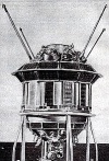
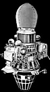
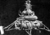
Lunik
II
Luna 2
#00114
(1959-014A) |
Luna 2 was the second
spacecraft launched in the direction of the Moon and
the first to land on the Moon. It impacted the lunar
surface east of Mare Serenitatis near the Aristides,
Archimedes, and Autolycus craters on September 14th
1959. Luna 2 was similar in design to Luna 1, a spherical
spacecraft with protruding antennae and instrument parts.
The instrumentation was also similar, including scintillation-
and geiger- counters, a magnetometer, and micrometeorite
detectors. The mission confirmed that the Moon had no
appreciable magnetic field, and found no evidence of
radiation belts at the Moon. |
Sept
12th 1959 |
390.2
kg |
This
recording of the Lunik II is from vinyl no. 8 which
was included in the Italian Enciclopaedia Luomo e lo
spazio (The man and the space) issued 1965 by Fratelli
Fabbri. Digitized and kindly provided by Federico Manzini. |
This
recording of the Lunik II was recorded by Heinz Kaminski
in Bochum at the moment when the space-probe crashed
on the surface of the moon. It is from vinyl no. 30
which was included in the Italian Enciclopaedia Luomo
e lo spazio (The man and the space) issued 1965 by Fratelli
Fabbri. Digitized and kindly provided by Federico Manzini. |
|
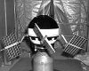
Lunik
III
Luna 3
#00021
(1959-008A) |
The lunar
probe Lunik 3, an automatic interplanetary station,
flew around the Moon. Recording kindly provided by Alois
DL3PD/SK. |
Oct
4th 1959 |
278.5
kg |
Luna
3 was the  first
probe which provided the signals and pictures (see on
the right) from far side of the Moon. In total it took
29 pictures. 17 pictures were successfully transmitted
back to Earth. Recording provided by Alois DL3PD/SK. first
probe which provided the signals and pictures (see on
the right) from far side of the Moon. In total it took
29 pictures. 17 pictures were successfully transmitted
back to Earth. Recording provided by Alois DL3PD/SK. |
This
recording of the Lunik III while it was 248000km away
from Earth was recorded on October 4th
1959. It is from vinyl no. 8 which was included in the
Italian Enciclopaedia Luomo e lo spazio (The man and
the space) issued 1965 by Fratelli Fabbri. Digitized
and kindly provided by Federico Manzini |
|
Pioneer
5
Pioneer V
#00027
1960-Alpha1
(1960-001A)
|
Pioneer 5 (1960 Alpha
1) was a spin-stabilized space probe used to investigate
interplanetary space between the orbits of earth and
Venus. The spacecraft measured magnetic field phenomena,
solar flare particles, and ionization in the interplanetary
region. The digital data were transmitted at 1, 8, and
64 bps, depending on the distance of the spacecraft
from the earth and the size of the receiving antenna.
|
Mar
11th 1960 |
43
kg |
This recording
of the Pioneer 5 is from vinyl no. 9 which was included
in the Italian Enciclopaedia Luomo e lo spazio (The
man and the space) issued 1965 by Fratelli Fabbri. Digitized
and kindly provided by Federico Manzini. |
|
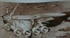
Ranger-4
#00280
(1962-012A) |
Ranger-4 was an automatic
lunar probe and was designed to transmit pictures of
the moon's surface before impacting the moon. An onboard
computer failure caused failure of the solar cell deployment.
Transmitted on 960 MHz with 50mWatt. Impacted on the
far side of the moon without returning any scientific
data. |
Apr
23rd 1962 |
331
kg |
Jules
Bergman from ABC Cape Canaveral reports about the launch
and the mission of Ranger-4. This recording is from
vinyl no. 43 which was included in the Italian Enciclopaedia
Luomo e lo spazio (The man and the space) issued 1965
by Fratelli Fabbri. Digitized and kindly provided by
Federico Manzini |
|
Ranger-5
#00439
(1962-055A) |
Ranger-5 was designed
to transmit pictures of the lunar surface to Earth stations
during a period of 10 minutes of flight prior to impacting
on the Moon, to rough-land a seismometer capsule on
the Moon, to collect gamma-ray data in flight, to study
radar reflectivity of the lunar surface and to continue
testing of the Ranger program for development of lunar
and interplanetary spacecraft. Due to an unknown malfunction,
the spacecraft ran out of power and ceased operation.
It passed within 725 km of the Moon. Ranger-5 transmitted
telemetry on 960 MHz (with 35 W). |
Oct. 18th
1962 |
342 kg |
This
recording is part of vinyl no. 57 which was included
in the Italian Enciclopaedia Luomo e lo spazio (The
man and the space) issued 1965 by Fratelli Fabbri. Digitized
and kindly provided by Federico Manzini |
|
Lunik
IV
Luna 4
#00566
(1963-008B) |
Luna 4 was
the USSR's first successful spacecraft of their "second
generation" lunar program. The spacecraft, also
referred to as an automatic interplanetary station was
launched on a Molniya 8K78 rocket. Rather than being
sent on a straight trajectory toward the Moon, the spacecraft
was placed first in a 167 x 182 km Earth orbit and then
was rocketed in a curving path towards the Moon. On
April 6th 1963 it passed over
the moon's surface in a distance of 8500 km. |
April
2nd 1963 |
1422
kg |
This
recording of the Lunik IV is from vinyl no. 59 which
was included in the Italian Enciclopaedia Luomo e lo
spazio (The man and the space) issued 1965 by Fratelli
Fabbri. Digitized and kindly provided by Federico Manzini |
|
Ranger-6
#00747
(1964-007A) |
Ranger-6 was designed
to achieve a lunar impact trajectory and to transmit
high-resolution photographs of the lunar surface during
the final minutes of flight up to impact. The frequency
of the tracking and data signal was 960.05 MHz. The
television transmitters of the dozen cameras operated
at 959.52 MHz and 960.58 MHz (each 60W). All camera
systems failed and thus no images were returned when
Ranger-6 impacted on the moon on February 2nd
1964. |
Jan. 30th
1964 |
381 kg |
This
recording is from the Observatory in Bochum/Germany
and is part of vinyl no. 67 which was included in the
Italian Enciclopaedia Luomo e lo spazio (The man and
the space) issued 1965 by Fratelli Fabbri. Digitized
and kindly provided by Federico Manzini |
|
Ranger-8
#01086
(1965-010A) |
Ranger
8 was launched on February 17th 1965 on an Atlas-Agena
B from Cape Canaveral, USA.  It reached the Moon
on February 20th 1965. The first
image was taken at 9:34:32 UTC at an altitude of 2510
km (see upper right picture). Transmission of 7,137
photographs of good quality occurred over the final
23 minutes of flight. It reached the Moon
on February 20th 1965. The first
image was taken at 9:34:32 UTC at an altitude of 2510
km (see upper right picture). Transmission of 7,137
photographs of good quality occurred over the final
23 minutes of flight.  The final image
taken before its impact in Mare Tranquilitatis has a
resolution of 1.5 meters (see lower right picture).
The spacecraft performance was excellent. The final image
taken before its impact in Mare Tranquilitatis has a
resolution of 1.5 meters (see lower right picture).
The spacecraft performance was excellent.
Communications
were achieved through the quasi omnidirectional low-gain
antenna and the parabolic high-gain antenna. Transmitters
aboard the spacecraft included a 60 W TV channel F at
959.52 MHz, a 60 W TV channel P at 960.05 MHz, and a
3 W transponder channel 8 at 960.58 MHz. The telecommunications
equipment converted the composite video signal from
the camera transmitters into an RF signal for subsequent
transmission through the spacecraft high-gain antenna.
Sufficient video bandwidth was provided to allow for
rapid framing sequences of both narrow- and wide-angle
television pictures. |
Feb. 17th
1965 |
367 kg |
In early 2020 Christian
Schwarze was able to acquire an old tape dated February
19-20th 1965, which had the
name Ranger 8 written on its box. He sent the tape to
me and I digitized it. It contains 30 minutes of several
reportages, most likely all of them from NBC News, covering
the launch of Ranger 8 and the presentation of its excellent
results in terms of pictures of the moon surface.
|
This first
recording is covering the launch of Ranger 8 on February
17th 1965. The report is from
NBC News at Cape Kennedy. Tape was kindly provided
by Christian Schwarze. |
This second
report is from a "7pm report" with the reporter
being at JPL summarizing the mission of Ranger 8. Tape
was kindly provided by Christian Schwarze. |
|
Ranger-9
#01294
(1965-023A) |
Ranger 9 was the last
of the Ranger satellites. It transmitted high-resolution
photographs of the lunar surface during the final minutes
of its flight before it impacted the moon. The spacecraft
carried six television vidicon cameras, 2 full-scan
cameras (channel F, one wide-angle, one narrow-angle)
and 4 partial scan cameras (channel P, two wide-angle,
two narrow-angle) to accomplish these objectives. After
64.5 hours of flight, impact occurred at 14:08:19.994
UT at 12.828 S latitude, 357.613 E longitude |
Mar. 21st
1965 |
367 kg |
This
recording of the last 40 seconds before Ranger-9 impacted
the lunar surface is part of the compilation "The
Conquest of Space" of the Astronautical Society
of Western Australia and kindly provided by Jos Heymann. |


|
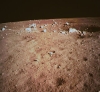
Luna-9
#01954
(1966-006A) |
On February 3rd
1966 the Russian moon probe Luna-9 was the first unmanned
probe which landed softly on the moon surface. |
Jan.
31st 1966 |
100
kg |
 This recording
of the transmission of Luna-9 after its soft landing
on the lunar surface was received by Jodrell-Bank-Radioobservatory
in UK with its 76m dish. They also published the first
picture of the moon surface captured and transmitted
by Luna-9. Recording kindly provided by Christian Schwarze. This recording
of the transmission of Luna-9 after its soft landing
on the lunar surface was received by Jodrell-Bank-Radioobservatory
in UK with its 76m dish. They also published the first
picture of the moon surface captured and transmitted
by Luna-9. Recording kindly provided by Christian Schwarze.
|
|
Luna-16
#04527
(1970-072A) |
Luna
16 was an unmanned space mission, part of the Soviet
Luna program. It was the
first robotic probe to land on the Moon and return a
sample of lunar soil to Earth. The sample mass was 101g
and was retrieved from Sea of Fertility (Mare Fecunditatis).
Analysis of the dark basalt material indicated a close
resemblance to soil recovered by the American Apollo
12 mission. According to the Bochum Observatory in Germany
strong and good quality television pictures were returned
by the spacecraft. However as Luna-16 landed at night
and its artificial
illumination failed unpublished panoramic images are
reported to contain only a few light spots seen in Earthlight.
Luna 16 was a landmark success for the
Soviets in their deep space exploration program; the
mission accomplished the first fully automatic recovery
of soil samples from the surface of an extraterrestrial
body. |
Sept. 12th
1970 |
5600 kg |
|
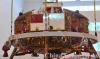
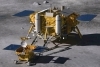
Luna-17
Lunik 17
Luna YE-8
Lunochod-1
Lunokhod-1
YE-8-203
#04691
(1970-095A) |
 Luna-17
included a moon rover. It was launched on Nov. 10th
1970 at 15:44h UTC from Baikonur cosmodrome by a four-stage
Proton rocket into 192 x 237 kilometre orbit with 51.5°
inclination around the Earth and then one hour later
the orbit was changed to send the spaceprobe to the
moon. Lunochod-1 landed softly on the moon on Nov 17th
1970 and manouvered across the moon surface providing
scientific data including TV images. Luna-17
included a moon rover. It was launched on Nov. 10th
1970 at 15:44h UTC from Baikonur cosmodrome by a four-stage
Proton rocket into 192 x 237 kilometre orbit with 51.5°
inclination around the Earth and then one hour later
the orbit was changed to send the spaceprobe to the
moon. Lunochod-1 landed softly on the moon on Nov 17th
1970 and manouvered across the moon surface providing
scientific data including TV images.
|
Nov. 10th
1970 |
5600 kg |
|
Lunik
20
Luna-20 return craft
#05835
(1972-007A) |
Luna 20
was placed in an intermediate earth parking orbit and
from this orbit was sent towards the Moon. It entered
lunar orbit on February 18th
1972. On February 21st 1972
Luna 20 soft landed on the Moon in a mountainous area
known as the Apollonius highlands near Mare Foecunditatis
(Sea of Fertility), 120 km from where Luna 16 had impacted.
While on the lunar surface, the panoramic television
system was operated. Lunar samples were obtained by
means of an extendable drilling apparatus. The ascent
stage of Luna 20 was launched from the lunar surface
on February 22nd 1972 carrying
30 grams of collected lunar samples in a sealed capsule.
It landed in the Soviet Union on February 25th
1972 and the lunar samples were recovered the following
day.
Enclosed signal was recorded on 183.54 MHz
on February 25th 1972 by Sven
Grahn. |
Feb 14th
1972 |
5600 kg |
|
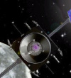
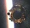
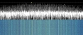
Smart-1
moon Orbiter
#27949
(2003-043C) |
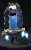
Smart-1 was launched
by ESA on an Ariane 5G rocket from Kourou. Mission
ended September 3rd 2006 with its planned impact into
moon. It transmitted at 2235.1
MHz, 8453.024225 MHz and at 32121.49350
MHz. |
Sep 27th 2003 |
367 kg |
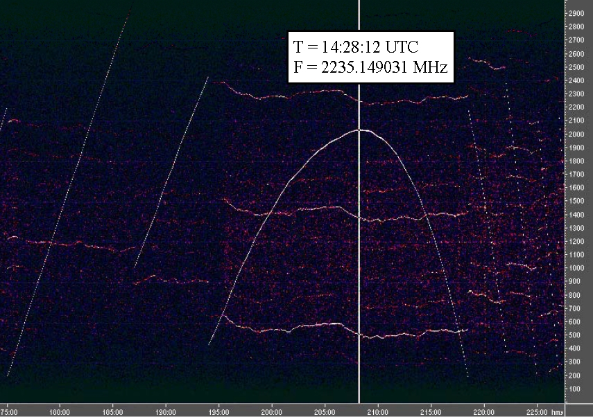
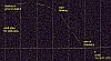
 Enclosed
audiogram was recorded at 2235.1 MHz on October 26th
2003 from 10:59 until 15:00 UTC. An unmodulated carrier
with initially rising positive Doppler shift and a frequency
inflection at 14:28:12 was received from the 5W transmitter
of Smart-1. This means that the point of maximum relative
approach speed was observed at the inflection point.
The audiogram displays a spectrogram of the observed
signal around the frequency inflection point. The positively
sloped lines before frequency inflection and the negatively
sloped lines after the inflection illustrate the stepwise
frequency tuning that was necessary to keep the audio
signal within the receivers 2.8 kHz USB bandpass. Audiogram
kindly provided by Edgar J. Kaiser DF2MZ. Enclosed
audiogram was recorded at 2235.1 MHz on October 26th
2003 from 10:59 until 15:00 UTC. An unmodulated carrier
with initially rising positive Doppler shift and a frequency
inflection at 14:28:12 was received from the 5W transmitter
of Smart-1. This means that the point of maximum relative
approach speed was observed at the inflection point.
The audiogram displays a spectrogram of the observed
signal around the frequency inflection point. The positively
sloped lines before frequency inflection and the negatively
sloped lines after the inflection illustrate the stepwise
frequency tuning that was necessary to keep the audio
signal within the receivers 2.8 kHz USB bandpass. Audiogram
kindly provided by Edgar J. Kaiser DF2MZ.
|
 Enclosed
spectrum plot was recorded at 8453 MHz on August 15th
2006 and was kindly provided by www.uhf-satcom.com. Enclosed
spectrum plot was recorded at 8453 MHz on August 15th
2006 and was kindly provided by www.uhf-satcom.com.
|
|
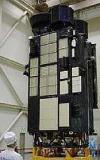
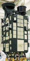
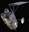
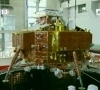
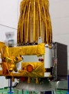
Selene
Kaguya
#32054
(2007-039A) |
SELenological and ENgineering
Explorer was funded by the Japan Aerospace Exploration
Agency. This lunar orbiter mission consists of three
satellites:
1.) an orbiter containing most of the
scientific equipment named "Kaguya"
2.)
a VLBI (Very Long Baseline Interferometry) Radio (VRAD)
satellite named "Ouna"
3.) a relay satellite
named "Okina" designed to receive a doppler
ranging signal from the orbiter when it is around the
far side of the moon out of direct contact with the
Earth and transmit the signal to Earth to estimate the
far-side gravitational field. |
Sep 14th 2007 |
1984 kg |
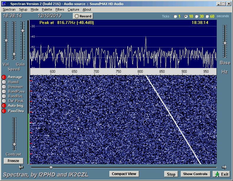
The S-band
downlink of Kaguya at 2363.6 MHz was received by Michael
OH2AUE using only a bent paper clip as the antenna.
This is to show what is possible with even such a small/simple
antenna: the signal is really weak but you can clearly
identify it especially at the end of the recording.
Recorded on December 18th 2007 by Michael OH2AUE. |
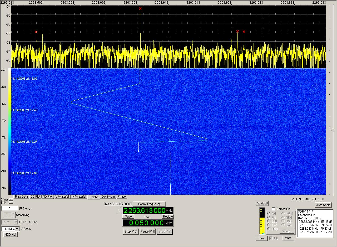
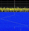 This
is a spectrum plot recorded by Paul M0YET on November
14th 2008 at 21:12 UTC. Please note the excellent signal
quality: he achieved more than 30 dB SNR using a 7 Hz
bandwidth. This
is a spectrum plot recorded by Paul M0YET on November
14th 2008 at 21:12 UTC. Please note the excellent signal
quality: he achieved more than 30 dB SNR using a 7 Hz
bandwidth.
|
|
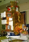
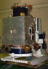
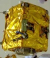
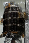
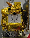
Chandrayaan
1
#33405
(2008-052A) |
Chandrayaan-1 (means
"Moon Craft" in ancient Sanskrit) is an Indian
Space Research Organization (ISRO) mission designed
to orbit the Moon over a two year period with the objectives
of upgrading and testing India's technological capabilities
in space and returning scientific information on the
lunar surface. The satellite is a cubic in shape of
approximately 1.5 m side. The scientific payload data
transmission is in X-band frequency. The Telemetry,
Tracking & Command (TTC) communication is in S-band
frequency. Chandrayaan includes also a Moon
Impact Probe (MIP)
weighing 29 kg which rides piggyback on the top deck
of the main orbiter. MIP is shown on the bbottom picture
to the left and will be released at a predetermined
time after the orbiter reaches the final 100 km orbit
to impact at a pre-selected location. MIP operates at
4.3 GHz +/- 100 MHz. |
Oct
22nd
2008 |
523
kg |
This spectrum plot of the
S-band downlink at 2230.9 MHz was recorded on November
8th 2008 by Paul Marsh M0YET. |
Here
is another recording of Chandrayaan-1 kindly provided
by Paul M0YET. He received the satellite on 2230,9 MHz
when rather far away and thus quite weak on November
9th 2008 at 19:53UTC using a 90cm dish and an AOR AR-5000
receiver. The satellite can barely be heard in the audio
file but very well seen in the spectrum plot. |
The X-Band
downlink (8483.967 MHz) of Chandrayaan-1 was recorded
by Paul M0YET on February 7th 2009 at 18:56UTC. |
|
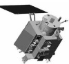
Lunar
Reconaissance Orbiter
LRO
(2009-031A) |
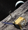
The Lunar
Reconnaissance Orbiter (LRO) was the first mission of
NASA's Robotic Lunar Exploration Program launched on
an Atlas V401 rocket from Cape Canaveral. LRO was designed
to map the surface of the Moon and has forever changed
our view of the moon, literally bringing it into sharper
focus and showing us the whole globe in unprecedented
detail. |
June
18th 2009 |
500
kg |
Enclosed
signal was received on December 28th
2011 at 19:34 UTC on 2271.223 MHz with a RHCP antenna
and kindly provided by Paul Marsh M0YET. |
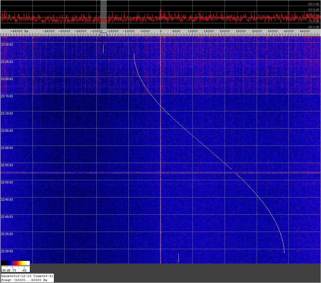
 On
December 10th 2013 at 23:30
UTC DF2MZ recorded a complete orbit of LRO on 2271.5
MHz. At the beginning and end of the orbit you can see
strong frequency jumps of the downlink signal when the
transmitter is switched from non-coherent to coherent
mode and vice versa. The strong doppler shift of the
signal results from viewing the satellite orbit from
the side. Spectrum plot recorded kindly provided by
Edgar J. Kaiser DF2MZ. On
December 10th 2013 at 23:30
UTC DF2MZ recorded a complete orbit of LRO on 2271.5
MHz. At the beginning and end of the orbit you can see
strong frequency jumps of the downlink signal when the
transmitter is switched from non-coherent to coherent
mode and vice versa. The strong doppler shift of the
signal results from viewing the satellite orbit from
the side. Spectrum plot recorded kindly provided by
Edgar J. Kaiser DF2MZ.
|
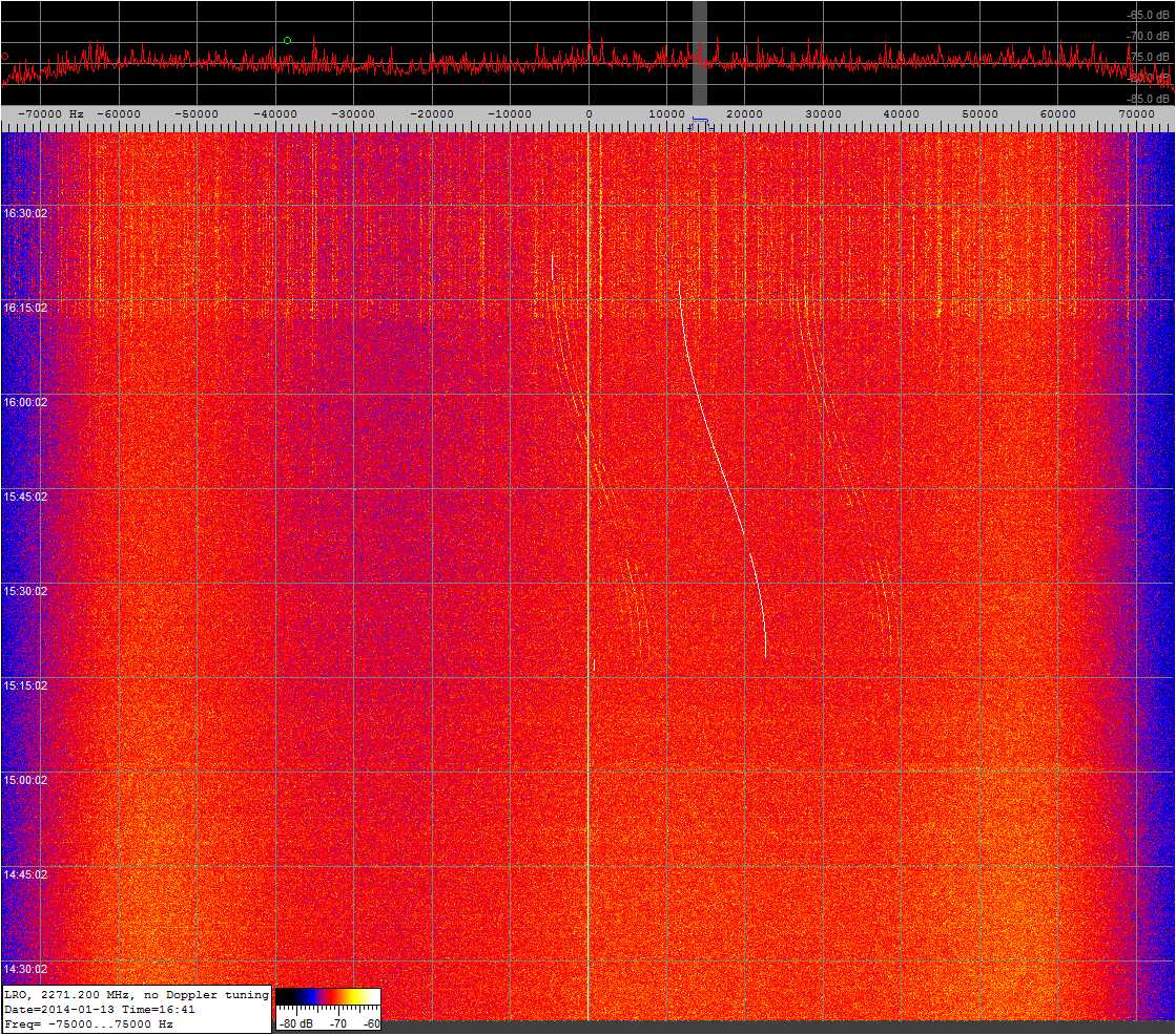
 Also
on January 13th 2013 at 16:40
UTC DF2MZ recorded a complete orbit of LRO on 2271.5
MHz. Much weaker doppler shift as this time the satellite
orbit was viewed almost orthogonally. Spectrum plot
recorded kindly provided by Edgar J. Kaiser DF2MZ. Also
on January 13th 2013 at 16:40
UTC DF2MZ recorded a complete orbit of LRO on 2271.5
MHz. Much weaker doppler shift as this time the satellite
orbit was viewed almost orthogonally. Spectrum plot
recorded kindly provided by Edgar J. Kaiser DF2MZ.
|
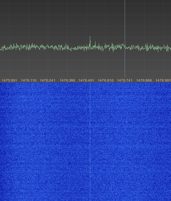
 The
S-Band TT&C downlink of LRO on 2271.5 MHz was received
and enclosed FFT plot was generated in May 2014 by Milen
Rangelov. The
S-Band TT&C downlink of LRO on 2271.5 MHz was received
and enclosed FFT plot was generated in May 2014 by Milen
Rangelov.
|
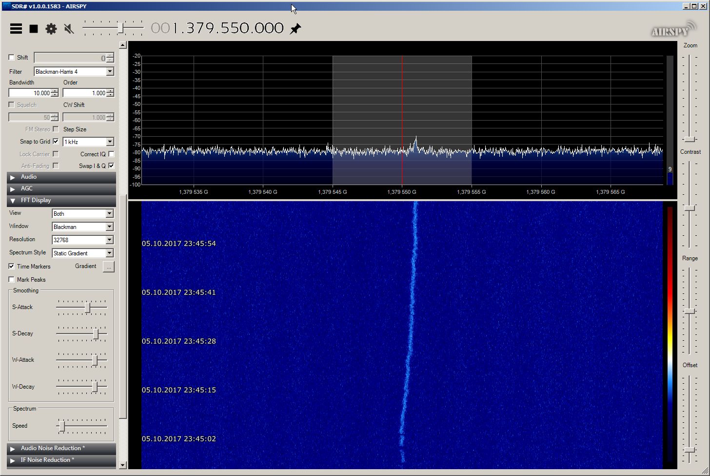
 On
October 5th 2017 at 21:45 UTC
I received the downlink of LRO. I used a 2.3m dish with
a linear feed and an Arabsat downconverter with a local
oscillator of ca. 3650 MHz. Total noise figure of the
system is estimated to be ca. 4 dB. On
October 5th 2017 at 21:45 UTC
I received the downlink of LRO. I used a 2.3m dish with
a linear feed and an Arabsat downconverter with a local
oscillator of ca. 3650 MHz. Total noise figure of the
system is estimated to be ca. 4 dB.
|
|
GRAIL
A & B
Ebb & Flow
Discovery 11
#37801
& #37802
(2011-046A &
2011-046B) |
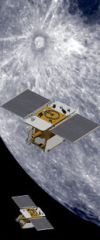
The GRAIL (Gravity Recovery
And Interior Laboratory) mission consists of two spacecrafts
(Grail A & B) which were jointly launched on a Delta
II rocket from Cape Canaveral. The mission objective
is to determine the structure of the lunar interior
and to advance understanding of the thermal evolution
of the Moon. S-band is used for communication with Earth
(TT&C) as well as for inter-satellite communication.
Grail A transmits on 2279.503 MHz while Grail B transmits
on 2280.592 MHz. A Ka-band payload, the Lunar Gravity
Ranging System (LGRS) will be used to allow high precision
range-rate measurements between the two spacecrafts.
Furthermore the spacecrafts feature low power X-band
tracking beacons (around 300 mW EIRP). Grail A transmits
on 8451.5995 MHz while Grail B transmits on 8451.7995
MHz. |
Sept.
9th
2011 |
each
133 kg |
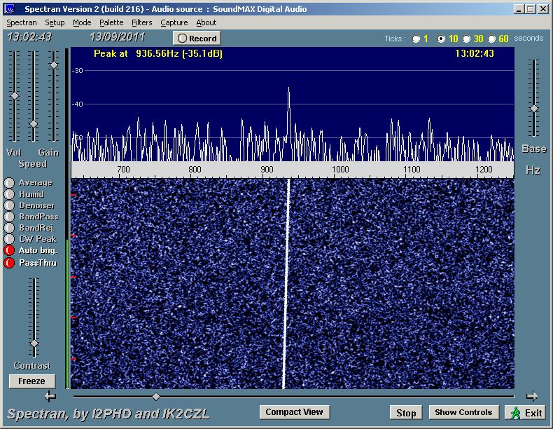
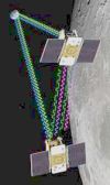
On September 13h
2011 around midday Paul Marsh M0EYT was able to receive
all 4 signals from the 2 spacecrafts while they were
about 400 000 km away from Earth on their way to the
moon orbit.
 This recording
of the S-Band signal from Grail A on 2279.503 MHz was
recorded on September 13th
2011 at 13:02 UTC. Recording and spectrum plot kindly
provided by M0EYT. This recording
of the S-Band signal from Grail A on 2279.503 MHz was
recorded on September 13th
2011 at 13:02 UTC. Recording and spectrum plot kindly
provided by M0EYT.
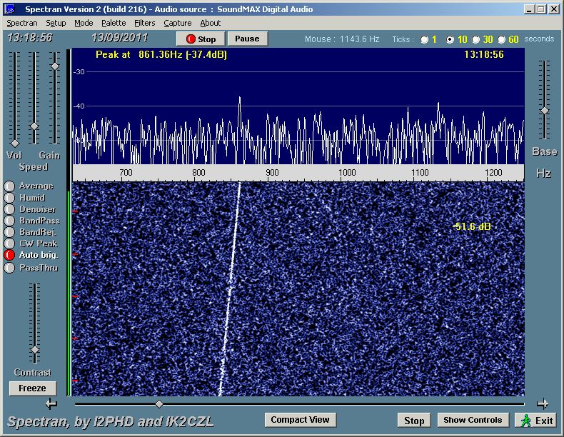
 This recording
of the X-Band signal from Grail A on 8451.5995 MHz was
recorded on September 13th
2011 at 13:19 UTC. Recording and spectrum plot kindly
provided by M0EYT. This recording
of the X-Band signal from Grail A on 8451.5995 MHz was
recorded on September 13th
2011 at 13:19 UTC. Recording and spectrum plot kindly
provided by M0EYT.
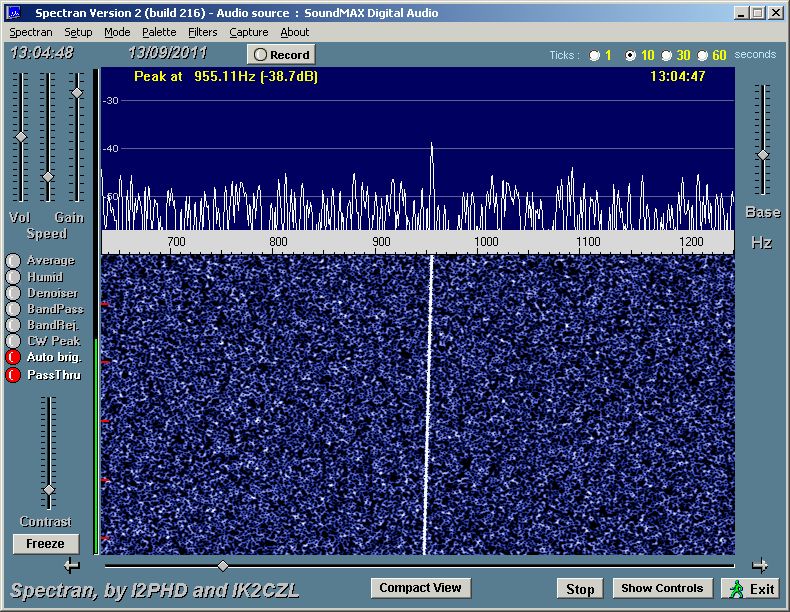
 This recording
of the S-Band signal from Grail B on 2280.592 MHz was
recorded on September 13th
2011 at 13:05 UTC. Recording and spectrum plot kindly
provided by M0EYT. This recording
of the S-Band signal from Grail B on 2280.592 MHz was
recorded on September 13th
2011 at 13:05 UTC. Recording and spectrum plot kindly
provided by M0EYT.
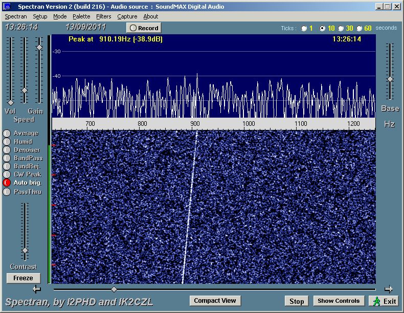
 This recording
of the X-Band signal from Grail B at 8451.7995 MHz was
recorded on September 13th
2011 at 13:26 UTC. Recording and spectrum plot kindly
provided by M0EYT. This recording
of the X-Band signal from Grail B at 8451.7995 MHz was
recorded on September 13th
2011 at 13:26 UTC. Recording and spectrum plot kindly
provided by M0EYT.
  This recording
of the S-Band signal from Grail A at2280.487 MHz was
recorded on December 31st 2011
at 16:45 UTC only a few minutes before the boosters
of Grail A were again activated and Grail entered into
an initially highly elliptical orbit around the Moon.
Recording and spectrum plots kindly provided by Paul
Marsh M0EYT. This recording
of the S-Band signal from Grail A at2280.487 MHz was
recorded on December 31st 2011
at 16:45 UTC only a few minutes before the boosters
of Grail A were again activated and Grail entered into
an initially highly elliptical orbit around the Moon.
Recording and spectrum plots kindly provided by Paul
Marsh M0EYT.
|
|
LADEE
#39246
(2013-047A) |
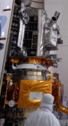
The Lunar Atmosphere
and Dust Environment Explorer (LADEE) is a NASA lunar
exploration mission by NASA. It was launched on a Minotaur
V rocket from the Mid-Atlantic Regional Spaceport on
September 7th 2013 at 03:27 UTC. The mission has 3 major
goals:
- determine the global density, composition
and time variability of the lunar exoshphere
- determine
if the Apollo astronaut sightings of diffuse emissions
at tens of kilometers above the surface were sodium
glow or dust
- document the dust impactor environment |
Sept.
7th
2013 |
248
kg |
 LADEE
was received on October 12th
2013 at 18:38 UTC on 2248.5 MHz while it was in moon
orbit. Enclosed recording and spectrum plot kindly provided
by Paul Marsh M0EYT. LADEE
was received on October 12th
2013 at 18:38 UTC on 2248.5 MHz while it was in moon
orbit. Enclosed recording and spectrum plot kindly provided
by Paul Marsh M0EYT.
|
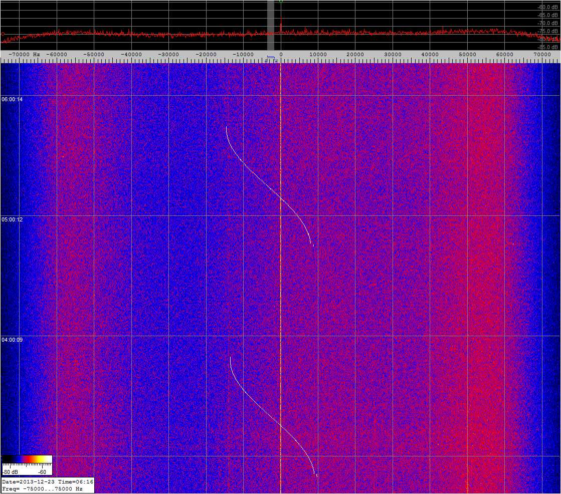
 On
December 23rd 2013 between
03:45 and 5:45 UTC DF2MZ recorded 2 complete orbits
of LADEE on 2248.5 MHz. Spectrum plot recorded kindly
provided by Edgar J. Kaiser DF2MZ. On
December 23rd 2013 between
03:45 and 5:45 UTC DF2MZ recorded 2 complete orbits
of LADEE on 2248.5 MHz. Spectrum plot recorded kindly
provided by Edgar J. Kaiser DF2MZ.
|
|
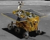
Chang'e-3
CE 3
YUTU
#39458
(2013-070A) |
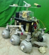
Chang'e 3 comprises two
modules, a Service Module and a Lunar Landing Vehicle
(LLV) with a total mass of 3700 - 3800 kg. The Change-3
mission is comprised of Chinas Yutu lunar lander
riding piggyback atop a much larger four legged landing
probe. The voyage from the Earth to the Moon began with
the flawless launch of Chang'e-3 atop Chinas Long March
3-B booster at 1:30 a.m. Beijing local time, December
2nd, 2013 from the Xichang
Satellite Launch Center, in southwest China. Change-3
made a powered descent to the Moons surface on Dec.
14th by firing the landing
thrusters at the altitude of 15 km (9 mi) for a soft
landing in a preselected area on the Bay of Rainbows. |
Dec.
1st
2013 |
3700
kg |
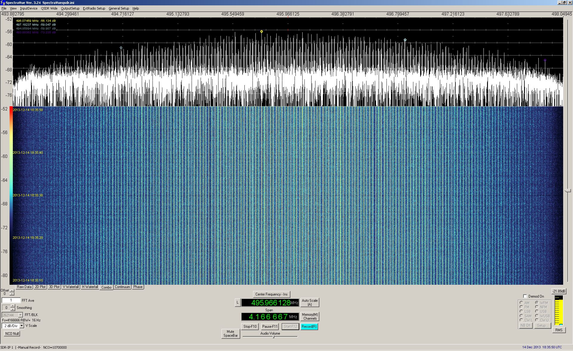
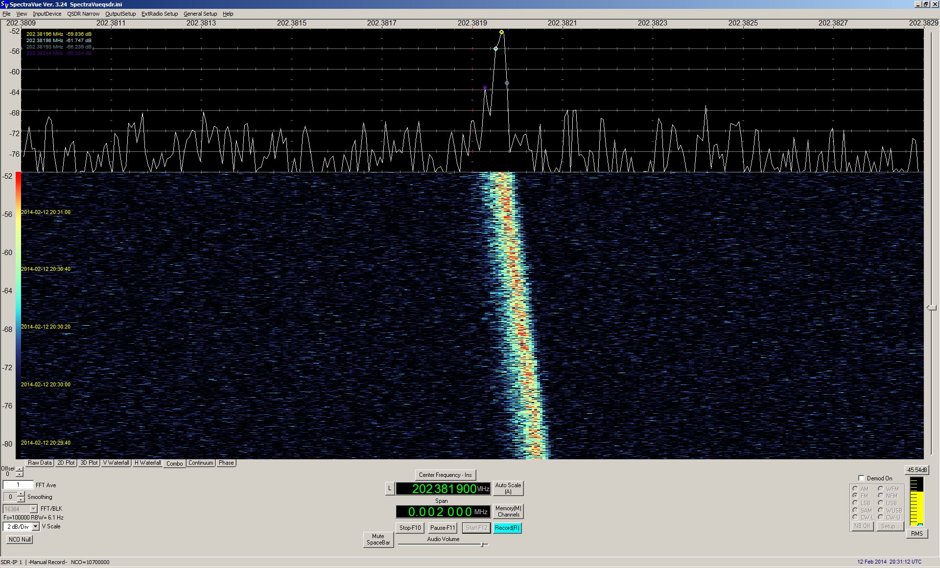
Signals of Chang'e 3
transmitting on 8496 MHz and the Rover YUTU transmitting
on 8462.08 MHz were received by Paul Marsh on December
14th 2013. |
 Audio
recording and spectrum plot of Chang'e 3 received on
December 14th 2013 at 18:35
UTC on 8496 MHz by M0EYT. Recording and spectrum plot
kindly provided by Paul Marsh M0EYT. Audio
recording and spectrum plot of Chang'e 3 received on
December 14th 2013 at 18:35
UTC on 8496 MHz by M0EYT. Recording and spectrum plot
kindly provided by Paul Marsh M0EYT.
|
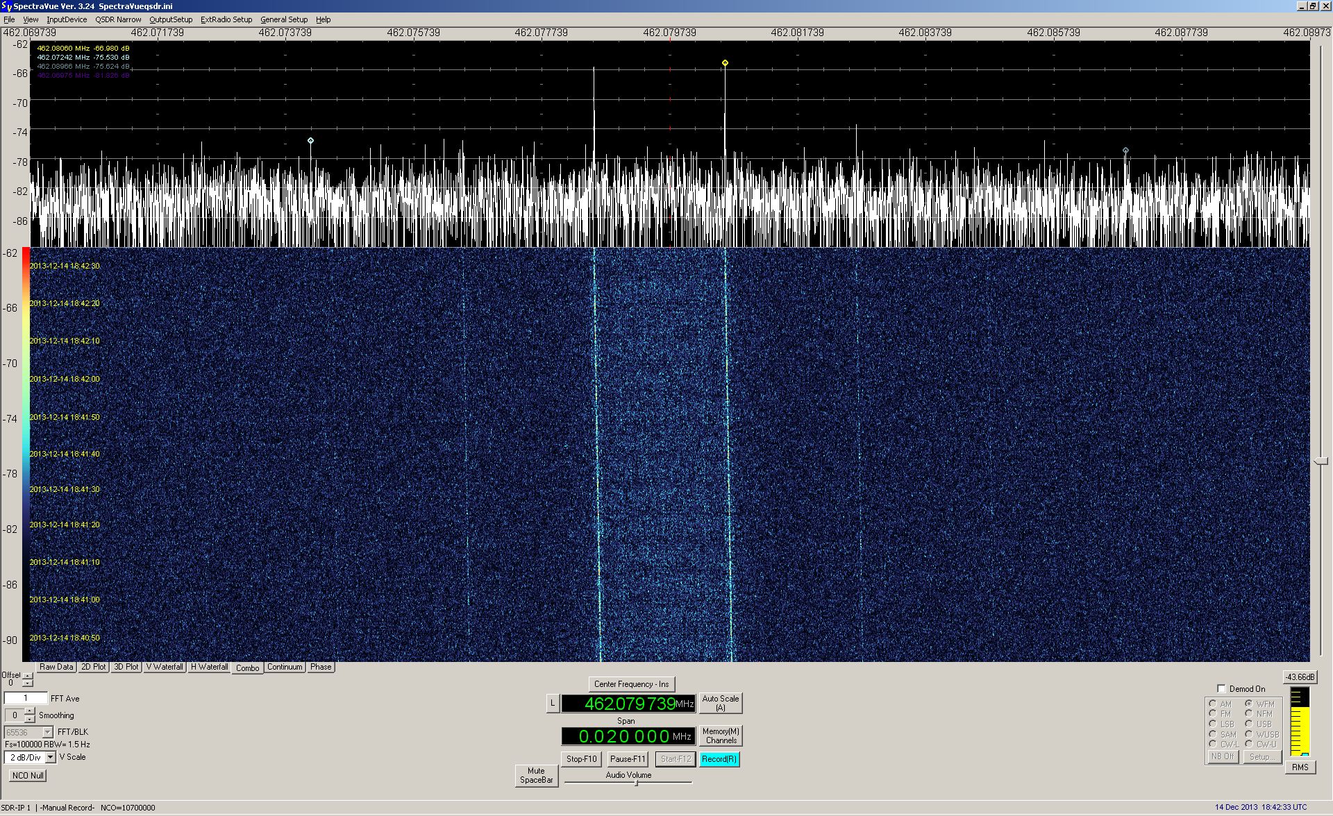
 Audio
recording and spectrum plot of the rover YUTU received
on December 14th 2013 at 18:41
UTC on 8462.08 MHz by M0EYT. Recording and spectrum
plot kindly provided by Paul Marsh M0EYT. Audio
recording and spectrum plot of the rover YUTU received
on December 14th 2013 at 18:41
UTC on 8462.08 MHz by M0EYT. Recording and spectrum
plot kindly provided by Paul Marsh M0EYT.
|
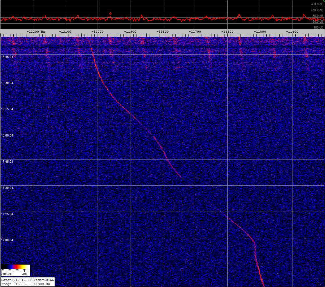
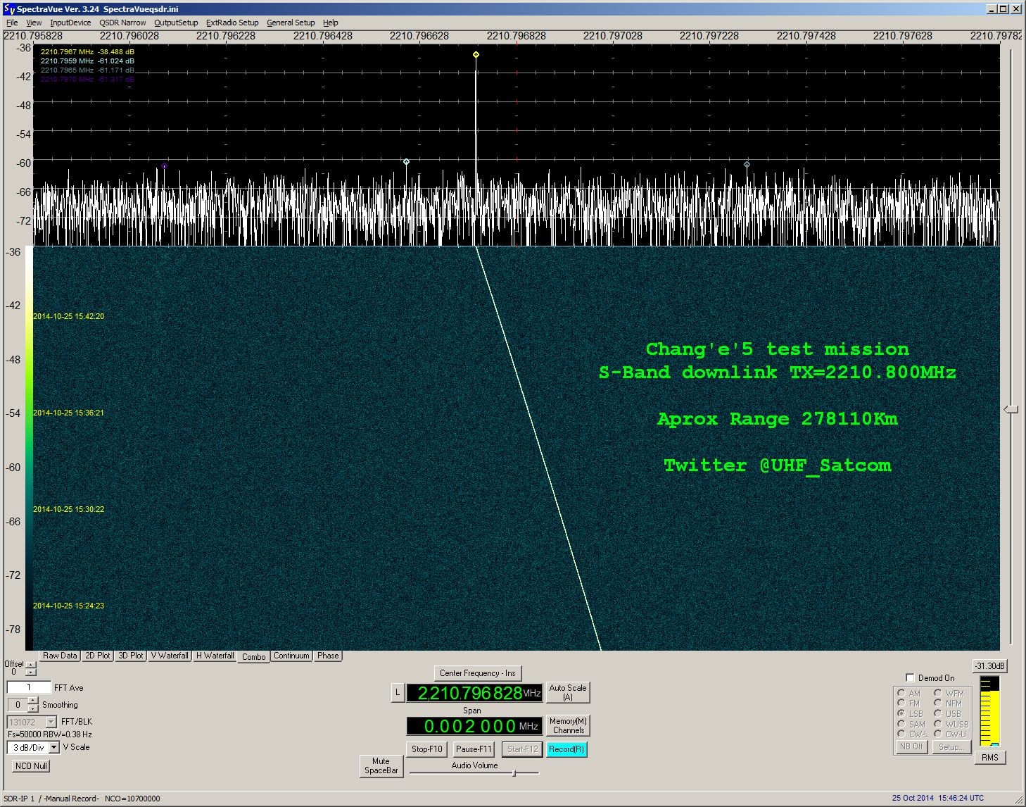
 Spectrum
plot of Chang'e 3 shortly before its LOI (lunar orbit
insertion) received on December 12th
2013 at 18:55 UTC on 2210.81 MHz by DF2MZ. Spectrum
plot kindly provided by Edgar J. Kaiser DF2MZ. Spectrum
plot of Chang'e 3 shortly before its LOI (lunar orbit
insertion) received on December 12th
2013 at 18:55 UTC on 2210.81 MHz by DF2MZ. Spectrum
plot kindly provided by Edgar J. Kaiser DF2MZ.
|
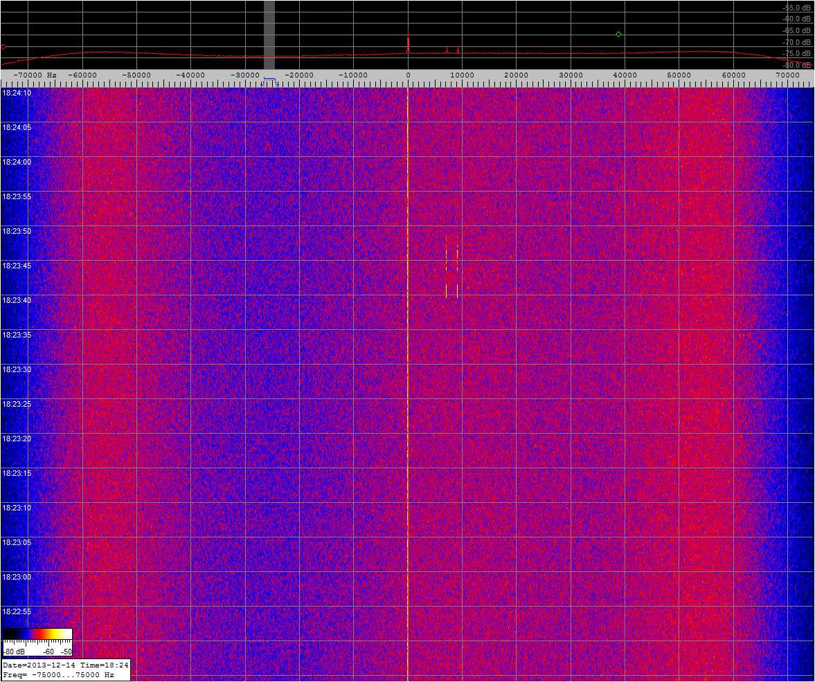
 Shortly
after the landing on the moon (still before the rover
was deployed) DF2MZ received some strong short bursts
on 8462.08 MHz from YUTU using only a small antenna
with only 15dB gain. Spectrum plot recorded on December
14th 2013 at 18:24 UTC and
kindly provided by Edgar J. Kaiser DF2MZ. Shortly
after the landing on the moon (still before the rover
was deployed) DF2MZ received some strong short bursts
on 8462.08 MHz from YUTU using only a small antenna
with only 15dB gain. Spectrum plot recorded on December
14th 2013 at 18:24 UTC and
kindly provided by Edgar J. Kaiser DF2MZ.
|
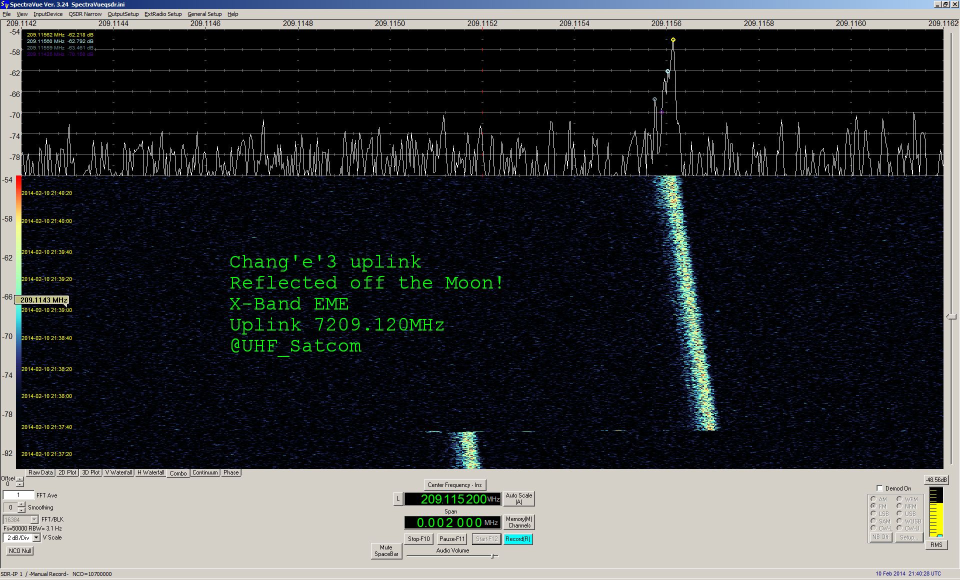
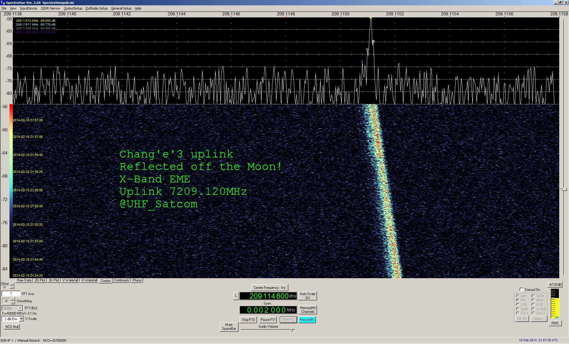
 On January
10th 2014 at 21:38 UTC Paul
M0EYT received not only the downlink signals from Chang'e-3
but also the uplink signal on On January
10th 2014 at 21:38 UTC Paul
M0EYT received not only the downlink signals from Chang'e-3
but also the uplink signal on  7.209
GHz reflected by the surface of the moon. Spectrum plot
and audio recording of the uplink signal kindly provided
by Paul Marsh M0EYT. 7.209
GHz reflected by the surface of the moon. Spectrum plot
and audio recording of the uplink signal kindly provided
by Paul Marsh M0EYT.
|
 Also on
January 12th 2014 at 20:30
UTC Paul M0EYT received the uplink signal on 7.203 GHz
reflected Also on
January 12th 2014 at 20:30
UTC Paul M0EYT received the uplink signal on 7.203 GHz
reflected  by
the surface of the moon. In addition he received the
downlink signal from the rover and proved that he had
survived the long lunar night. Spectrum plot and audio
recording of the uplink signal kindly provided by Paul
Marsh M0EYT. by
the surface of the moon. In addition he received the
downlink signal from the rover and proved that he had
survived the long lunar night. Spectrum plot and audio
recording of the uplink signal kindly provided by Paul
Marsh M0EYT.
|
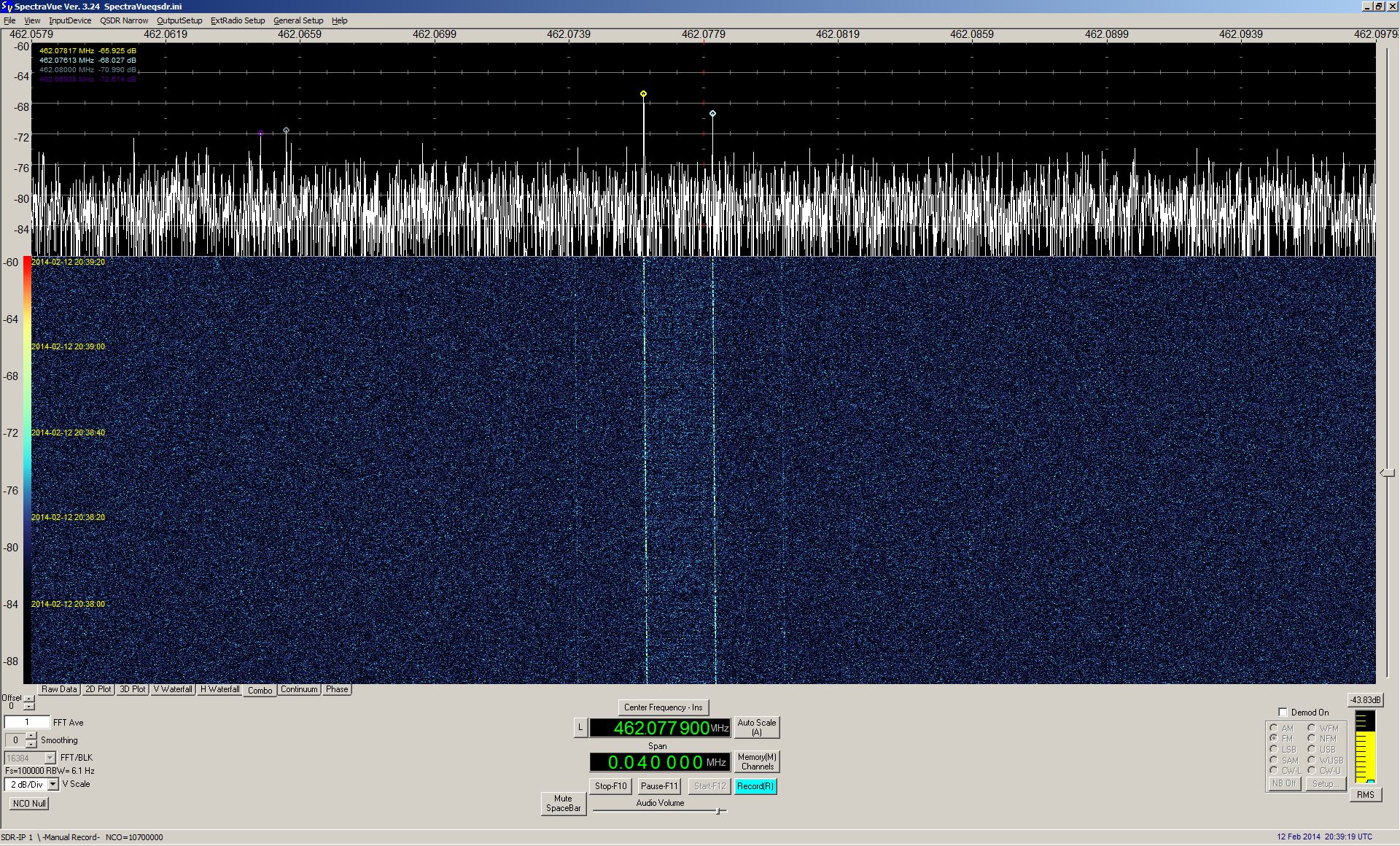
 On February
2nd 2015 at 19:57 UTC Paul
M0EYT received the downlink signal of YUTU On February
2nd 2015 at 19:57 UTC Paul
M0EYT received the downlink signal of YUTU  on
8.462036 GHz. Spectrum plots and audio recording kindly
provided by Paul Marsh M0EYT. on
8.462036 GHz. Spectrum plots and audio recording kindly
provided by Paul Marsh M0EYT.
|
 More
than 4 years after the start of the mission Edgar DF2MZ
received the signal from Chang'e-3 lunar lander on 8496
MHz, first the carrier and then the data signal. Spectrum
plot recorded on January 9th
2018 at 00:55 UTC and kindly provided by Edgar J. Kaiser
DF2MZ. More
than 4 years after the start of the mission Edgar DF2MZ
received the signal from Chang'e-3 lunar lander on 8496
MHz, first the carrier and then the data signal. Spectrum
plot recorded on January 9th
2018 at 00:55 UTC and kindly provided by Edgar J. Kaiser
DF2MZ.
|
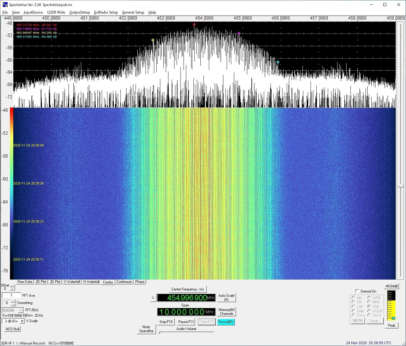
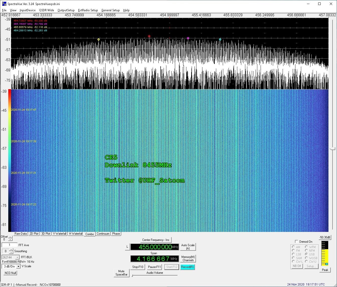
 About 7 years after its launch,
on November 24th 2020 Paul
M0EYT received the downlink signal of CE5 on 8.455 GHz. About 7 years after its launch,
on November 24th 2020 Paul
M0EYT received the downlink signal of CE5 on 8.455 GHz.
 Spectrum plots kindly provided
by Paul Marsh M0EYT. Spectrum plots kindly provided
by Paul Marsh M0EYT.
|
|
Chang'e
5-T1
CE 5-T1
#40283
(2014-065A) |
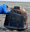
Chang'e
5-T1 (Chang'e 5 Test Vehicle) is a Chinese test mission
for the Chang'e 5 lunar sample return mission. It is
to validate the technology for the reentry vehicle.
Chang'e
5-T1 consists of a Chang'e 2 type spacecraft featuring
the Chang'e 5 return capsule. It was launched on October
23rd 2014 on a CZ-3C/G2 rocket.
The probe was on a free-return lunar orbit and made
a loop behind the Moon. Finally it successfully tested
a high speed atmospheric reentry of a capsule returning
from the moon. The return capsule landed successfully
on October 31st 2014
in China. |
Oct
23rd 2014 |
|
On October 24th
2014 Edgar J. Kaiser DF2MZ detected the downlink signal
on 2210.810 MHz. |
 Paul Marsh
M0EYT confirmed the finding and kindly provided enclosed
audio recording and spectrum plot. The audio was received
on October 28th 2014 on 2210.817
MHz whereas the spectrum plot was generated on October
25th 2014 at 15:45 UTC. Recording
and spectrum plot kindly provided by Paul M0EYT. Paul Marsh
M0EYT confirmed the finding and kindly provided enclosed
audio recording and spectrum plot. The audio was received
on October 28th 2014 on 2210.817
MHz whereas the spectrum plot was generated on October
25th 2014 at 15:45 UTC. Recording
and spectrum plot kindly provided by Paul M0EYT.
|
Before the reentry of
the return capsule, it separated from the service module
of China's test lunar orbiter. After performing several
orbital transfers, on November 29th
2014 the service module reached the Moon-Earth-L2 Lagrange
Point of the Earth-Moon-System at a distance from Earth
of about 449000 km. On November 29th
2014 Edgar J. Kaiser DF2MZ detected the downlink signal
of the service module on 2210.800 MHz again. |
 On January
8th 2015 at 22:37 UTC Edgar
DF2MZ received Chang'e 5-T1 on 2234.520 MHz while it
was on its way from Moon-Earth-L2 point to Moon orbit.
He used an 1m parabolic dish and a linear feed. Recording
and spectrum plot kindly provided by Edgar Kaiser DF2MZ. On January
8th 2015 at 22:37 UTC Edgar
DF2MZ received Chang'e 5-T1 on 2234.520 MHz while it
was on its way from Moon-Earth-L2 point to Moon orbit.
He used an 1m parabolic dish and a linear feed. Recording
and spectrum plot kindly provided by Edgar Kaiser DF2MZ.
|
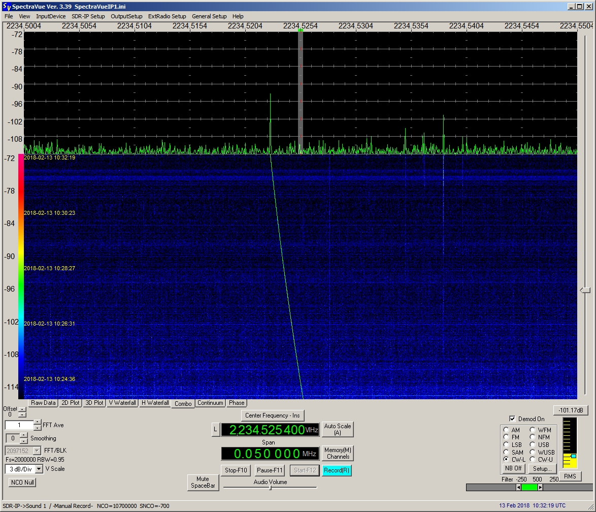
 On February
13th 2018 at 10:30 UTC DD1US
received the Chang'e 5-T1 moon orbiter on 2234.500 MHz. On February
13th 2018 at 10:30 UTC DD1US
received the Chang'e 5-T1 moon orbiter on 2234.500 MHz.
|

|
4M-LXS
4M
LX0OHB-4M
#40284
(2014-065B) |
On October 23rd
2014 LuxSpace (the Luxemburgian daughter company of
OHB in Germany) launched a small ham radio satellite
into a moon orbit. The mission has the name "4M-LXS"
or "Manfred Memorial Moon Mission" in memoriam
of Manfred Fuchs, the previous head of OHB. 4M-LXS was
launched with a Chinese test rocket together with the
lunar probe Chang'e 5-T1 (CE 5-T1) and it is located
on the Vehicle Equipment Bay of the 3rd
and last stage of the launcher. 4M-LXS sent telemetry
as well as prerecorded short messages. Mission duration
was expected from October 23rd
to October 31st 2014. Transmissions
were based on a 1 minute sequence and a 5 minute cycle.
4M-LXS transmitted on 145.980 MHz with 1.5 Watts into
a 2m monopole (lambda/4) antenna (resulting in an average
EIRP of -6dBW) using JT65B (WSJT) format. JT65B uses
multiple frequency shift keying (MFSK) with 65 tones
at 2.69 Baud. The effective throughput is 0.25 cps (characters
per second). Minimum requirements to receive 4M-LXS
were a 12dBic circular polarized directional antenna,
cable loss between antenna and LNA 0.5 dB, LNA NF<1dB,
SSB receiver (BW 2.5 kHz), WSJT software. This should
have resulted in a system temperature of 641°K and
thus in a minimum received signal of -158 dBm. The satellite
worked fine and many reception reports were received. |
Oct
23rd 2014 |
14
kg |
Enclosed
very strong downlink-signal was kindly provided by Ghislain
LX2RG from LuxSpace SARL. |
Enclosed
strong downlink-signal was received and kindly provided
by Ghislain LX2RG from LuxSpace SARL. |
|
Queqiao
Chang'e 4 Relay
CE 4 Relay
#43470
(2018-045A) |
Queqiao (Magpie
Bridge) , also known initially as Chang'e 4 Relay, is
a Chinese relay satellite mission in support of the
Chang'e 4 rover landing on the far site on the moon.
The
425 kg relay satellite is based on the three-axis stabilized
CAST-100 small satellite bus featuring an 130 N hydrazine
propulsion system. It carries a deployable 4.2 m dish
antenna for the relay equipment. It provides four 256
kBps X-band links between itself and the lander/rover
and one 2 MBps S-band link towards earth. Besides
the relay function, the spacecraft also carries the
Dutch NCLE Low-frequency radio detector to provide radio-sky
images, and frequency dependence of radio in the very
low frequency band and to perform low-frequency radio
astronomical observations. |
May
20th 2018 |
425
kg |
 On
May 21st 2018 at 20:17 UTC
Paul M0EYT received the modulated TTC downlink signal
of Queqiaoon 2234.502 MHz. Spectrum plots and audio
recording kindly provided by Paul Marsh M0EYT. On
May 21st 2018 at 20:17 UTC
Paul M0EYT received the modulated TTC downlink signal
of Queqiaoon 2234.502 MHz. Spectrum plots and audio
recording kindly provided by Paul Marsh M0EYT.
|
 Paul
also received an unmodulated downlink signal on 2230.777
MHz on May 21st 2018 at 20:35
UTC. Spectrum plots and audio recording kindly provided
by Paul Marsh M0EYT. Paul
also received an unmodulated downlink signal on 2230.777
MHz on May 21st 2018 at 20:35
UTC. Spectrum plots and audio recording kindly provided
by Paul Marsh M0EYT.
|
 On
May 22nd 2018 at 17:38 UTC
also DD1US received a strong signal from Queqiao on
its way to the moon. The sidebands of the signal are
not from the satellite but spurs of the receiver. Received
and recorded on 2234.507 MHz by DD1US. On
May 22nd 2018 at 17:38 UTC
also DD1US received a strong signal from Queqiao on
its way to the moon. The sidebands of the signal are
not from the satellite but spurs of the receiver. Received
and recorded on 2234.507 MHz by DD1US.
|
|
Lunar
OSCAR 93
DSLWP A1
DSLWP A
LongJiang
1
#43471
(2018-045B) |
DSLWP
A1 and A2 (Discovering the Sky at Longest Wavelengths
Pathfinder) are two identical Chinese lunar microsatellites
mission to perform ultra-long-wave astronomical observations
developed at the Harbin Institute of Technology (HIT).
The 47 kg micro-satellites were launched piggy-back
with Queqiao (Chang'e 4 Relay, but are to insert them
by themselves into 300 km × 9000 km elliptical
lunar orbits. The satellites are three-axis stabilized
and carry a radio-astronomy payload featuring two linear
polarization antennas mounted along and normal to the
flight direction, which uses the moon as a shield to
avoid radio emmanations from earth. Additionally, the
satellites carry a King Abdulaziz City for Science and
Technology (KACST) developed micro-optical camera. Finally,
the satellites also carry an amateur radio communications
system. Onboard each satellite, there are two VHF/UHF
SDR transceivers to provide beacon, telemetry, telecommand,
digital image downlink and a GMSK-JT4 repeater. Onboard
transmitting power is about 2 W. Radio Amateurs will
be able to receive telemetry downlinks but will also
be allowed to send telecommands for taking and downlinking
pictures. There are also plans to enable FreeDV digital
voice communications through this spacecraft.
Satellite A1 transmits
500 baud GMSK with 1/4 turbo code on 435.425 MHz and
250 baud GMSK with 1/2 turbo code and precoder on 436.425
MHz in every 5 minutes by default. Each transmission
lasts about 16 seconds.
Communication to
DSLWP was lost during a manoeuvre on its way to the
moon. |
May
20th 2018 |
47
kg |
 On
May 20th 2018 at 19:20 UTC
Roland PY4ZBZ received the downlink signal from DSLWP
A on 436.400MHz. On
May 20th 2018 at 19:20 UTC
Roland PY4ZBZ received the downlink signal from DSLWP
A on 436.400MHz.
 20
minutes later at 19:40 UTC on May 20th
2018 he received both satellites. 20
minutes later at 19:40 UTC on May 20th
2018 he received both satellites.
Spectrum plots
kindly provided by Roland PY4ZBZ. |
|
Lunar
OSCAR 94
DSLWP A2
DSLWP B
LongJiang
2
#43472
(2018-045C) |
DSLWP
A1 and A2 (Discovering the Sky at Longest Wavelengths
Pathfinder) are two identical Chinese lunar microsatellites
mission to perform ultra-long-wave astronomical observations
developed at the Harbin Institute of Technology (HIT).
The 47 kg micro-satellites were launched piggy-back
with Queqiao (Chang'e 4 Relay, but are to insert them
by themselves into 300 km × 9000 km elliptical
lunar orbits. The satellites are three-axis stabilized
and carry a radio-astronomy payload featuring two linear
polarization antennas mounted along and normal to the
flight direction, which uses the moon as a shield to
avoid radio emmanations from earth. Additionally, the
satellites carry a King Abdulaziz City for Science and
Technology (KACST) developed micro-optical camera. Finally,
the satellites also carry an amateur radio communications
system. Onboard each satellite, there are two VHF/UHF
SDR transceivers to provide beacon, telemetry, telecommand,
digital image downlink and a GMSK-JT4 repeater. Onboard
transmitting power is about 2 W. Radio Amateurs will
be able to receive telemetry downlinks but will also
be allowed to send telecommands for taking and downlinking
pictures. There are also plans to enable FreeDV digital
voice communications through thise spacecraft.
Satellite A2 transmits
500 baud GMSK with 1/4 turbo code on 435.400 MHz and
250 baud GMSK with 1/2 turbo code and precoder on 436.400
MHz in every 5 minutes by default. Each transmission
lasts about 16 seconds.
Lunar OSCAR 94
crashed into the far side of the moon on July 31st
2019 around 14:08 UTC ending its very successful amateur
radio mission around the moon. |
May
20th 2018 |
47
kg |
On
May 20th 2018 at 19:40 UTC
Roland PY4ZBZ received the downlink signals from DSLWP
A and DSLWP B.
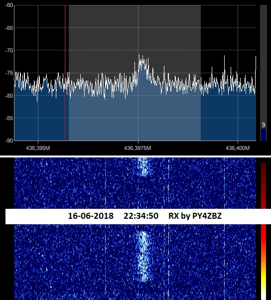
 On
June 16th 2018 at 22:34 UTC
Roland received the 250bd GMSK signal from DSLWP B. On
June 16th 2018 at 22:34 UTC
Roland received the 250bd GMSK signal from DSLWP B.
Spectrum plots
kindly provided by Roland PY4ZBZ. |
|
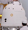
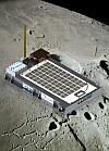
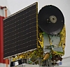
Beresheet
SpaceIL LUnar Lander
#44049
(2019-009B) |
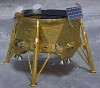
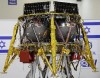
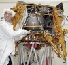
The
SpaceIL Lunar Lander or Beresheet (nicknamed "Sparrow"
during development) is a lunar lander developed by the
Israeli nonprofit organisation SpaceIL. It was originally
an entry to win the Google Lunar XPRIZE (GLXP).The SpaceIL
Lunar Lander is a lunar lander, which has a propulsion
system to enable itself to leave earth orbit and to
enter a trajectory to the moon. The lander is a four-legged
circular platform and has a launch mass of 585 kg, including
435 kg of fuel. It stands 1.5 meters high, and 2 meters
in diameter. Solar panels mounted on top of the spacecraft
deck provide power. The lander will carry imagers, a
magnetometer, and a laser retroreflector. It also carries
a digital time capsule of Israeli cultural and historic
artifacts. In October 2015, SpaceIL contracted via Spaceflight
Inc. a shared launch to earth orbit on a SpaceX Falcon-9
v1.2 (Block 5) rocket launched from Vandenberg. Later
it was rebooked on a launch with the PSN 6 communications
satellite to a supersynchroneous transfer orbit, also
on a Falcon-9 v1.2 (Block 5) rocket launched from Cape
Canaveral. Beresheet is scheduled to land on the moon
on April 11th 2019. |
Feb
22nd 2019 |
150
kg |
 On March
31st 2019 around 10:40 UTC
Edgar DF2MZ received Beresheet on 2280 MHz while it
was approaching perigee. On the waterfall diagram one
can see a ground station handover around 10:40 UT. Recording
and spectrum plot kindly provided by Edgar Kaiser DF2MZ. On March
31st 2019 around 10:40 UTC
Edgar DF2MZ received Beresheet on 2280 MHz while it
was approaching perigee. On the waterfall diagram one
can see a ground station handover around 10:40 UT. Recording
and spectrum plot kindly provided by Edgar Kaiser DF2MZ.
|
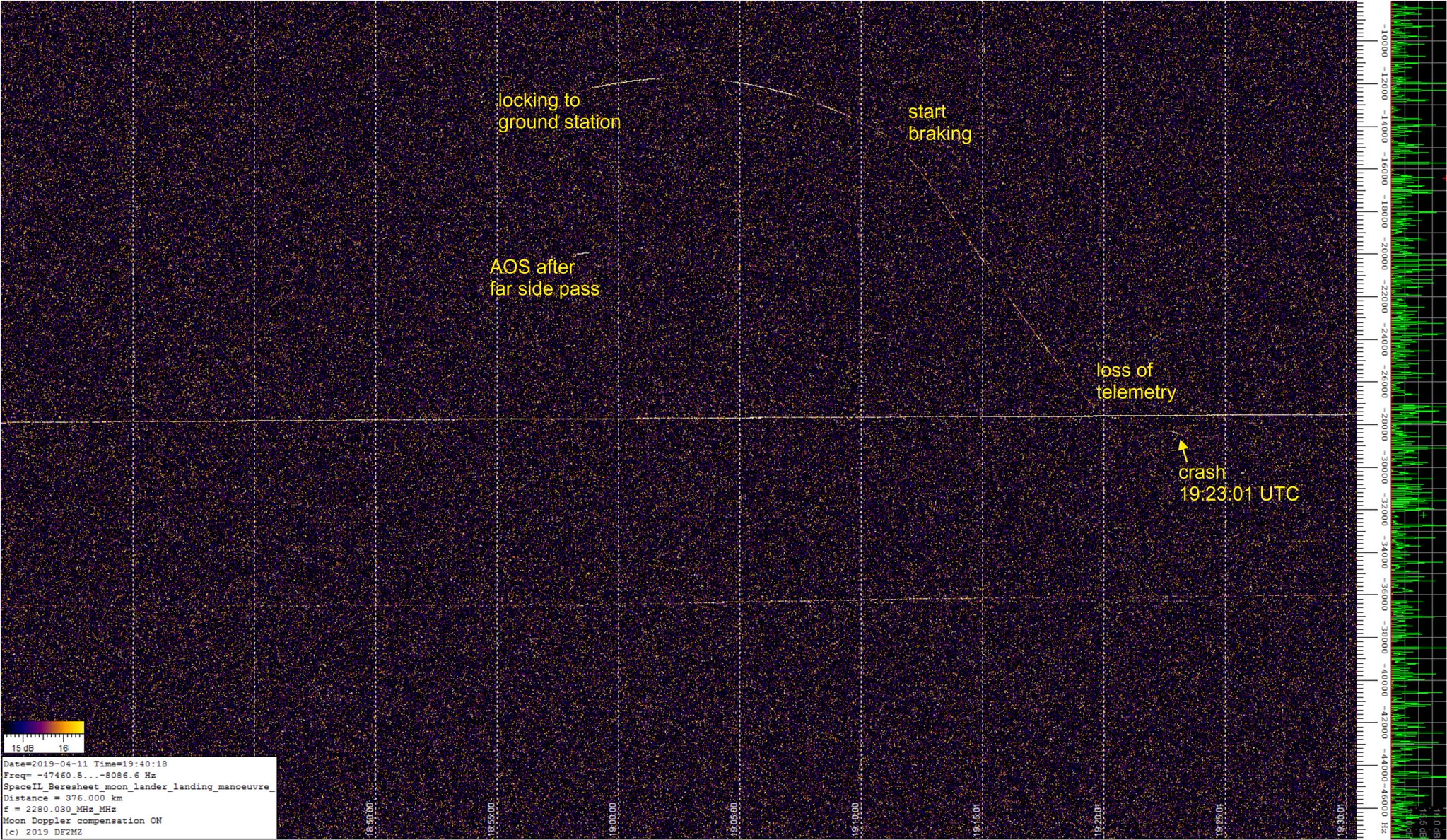
 DF2MZ
received Beresheet also during its last phase before
if crashed on the surface of the moon on April 11th
2019 at 19:23 UTC. Waterfall diagram kindly provided
by Edgar Kaiser DF2MZ. DF2MZ
received Beresheet also during its last phase before
if crashed on the surface of the moon on April 11th
2019 at 19:23 UTC. Waterfall diagram kindly provided
by Edgar Kaiser DF2MZ.
|
|
Chandrayaan
2
#43xxx
(2018-xxx) |
Chandrayaan-2 (means
"Moon Craft" in ancient Sanskrit) is the second
Indian Space Research Organization (ISRO) Moon mission.
Chandrayaan-2
is an advanced version of the previous Chandrayaan-1
mission. It consists of an orbiter, lander and rover
configuration. The orbiter with scientific payloads
will orbit around the Moon. The lander will soft-land
on the Moon at a specified site and deploy the rover.
The scientific payloads onboard the orbiter, lander
and rover are expected to perform mineralogical and
elemental studies of the lunar surface.
The synthetic aperture radar (SAR)
is operating in L-band. The Telemetry (SIT) and Tracking
& Command (TC) communication is in S-band frequency.
There is also a high bandwidth downlink in X-band.
ITU is listing the following frequencies:
Beam Frequ./MHz
Bandw./kHz
Class
LSAR 1250
70000
E1
LSAR1
1252.5
75000
E1
LSAR2
1250
75000
E1
OR-TC 2409.75
6
EH&ET
S1T 2217.12
500
EH&ET
S1T 2230.8
500
EH&ET
S1T 2283.84
500
EH&ET
SSAR 2500
75000
E1
X1T 8484
11000
EH |
mid April
2019 |
xxx kg |
Picture |
Object
name
#NORAD |
Description |
Launch
Date |
Weight |