Welcome to this section of my homepage,
which is dedicated to my hobby Amateur Radio, also called
Ham Radio. |
My name is Matthias Bopp and I am
a German radio amateur. I received my license in 1979
and since then I use the callsign:
   
I am a member
of the following amateur radio organizations: |

|
|

|

|
|
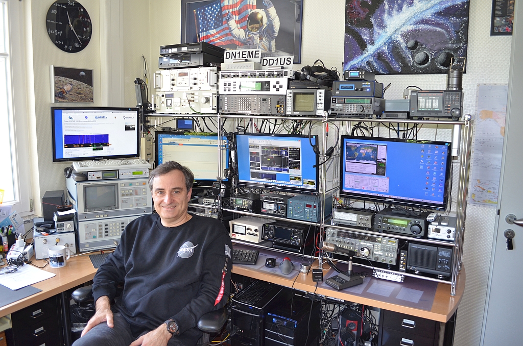
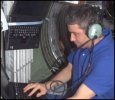
On
the upper right picture you can see me sitting in one
of my "Radio Shacks". "Shack", that's
how we radio amateurs call our room with the radio equipment
such as transceivers for various operations modes like
ATV, FAX, SSTV, FM, SSB, satellite communication and
Packet Radio. Radio amateurs have the privilege to build
and operate their equipment (e.g. receivers, transmitters,
amplifiers and antennas) on their own. To test these
devices I have acquired and built over time quite some
test equipment. |
We have multiple homes and thus I
happen to have several Radio Shacks and respective antenna
setups. |
The
home shown on the picture to the right is located in
the area of Heilbronn. It is an old house with a barn
and you can see my shack and some of my equipment on
the respective page when you click on the picture. |

|
|
We
also a home in the area of Freiburg/Breisgau. You can
find some more information about this station when clicking
on the picture to the left. The page is not yet complete
and I will post a more detailed description of the ham
radio station once it is fully set up. |
I
also use a little portable station when I am in our
summerhouse. I am mostly using this little station on
VHF/UHF but occasionally also operate on the upper HF
bands (10m, 15m and 20m). Please click on the picture
to the right to get to this page showing the setup and
examples of operation logs. |
|

|
I
am travelling quite a bit by car and enjoy staying in
touch with friends using my Kenwood TM-D710E dual-band
(2m, 70cm) mobile transceiver which also supports APRS. |
I
also use some handheld transceivers especially when
going for a walk. Please click on the picture to the
right to get to the respective page for portable operations. |

|
|
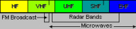
I
used to work mostly on VHF / UHF / SHF frequencies but
since 2003 also operate sometimes on the HF bands. If
you click on the picture to the left you get detailed
frequency allocation and amateur radio band plan information. |
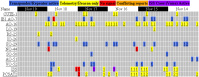
Propagation
conditions are different on the various frequency bands
and vary over time.
They are a function of a many
parameters including the status of the ionosphere. On
the table on the right you can see the present conditions
on HF and VHF. |
|
|
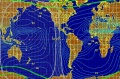
The
link on the left shows a map with the Maximum Usable
Frequencies (MUFs) for 3000 kilometer radio signal paths.
The map also shows the present grayline and other important
features for long distance contacts (DX). |
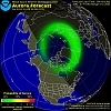
Especially
on HF but also on VHF and sometimes on UHF the magnetic
field of the earth has a strong impact on the propagation
of the respective waves. One of the associated phenomena
are reflections at Aurora zones which can influence
the propagation of radio waves and provide DX conditions.
On the right please find a link to the present status
of the Aurora oval over the Arctic. You can see how
strong it is and how far it extends to lower latitudes. |
|

|
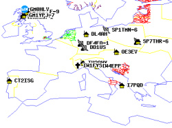
If
you want to know which DX stations are presently active
you can click on the icon on the left. The DX-Cluster
is an internet platform where stations on the various
bands are logged. You can thus find out which country
on which band can be presently reached. |
In
order to improve the operator's skills and also to get
more people active on the bands there are many "contests"
organized by the various amateur radio organizations
around the world. Clicking on the icon to the right
you will get to the excellent contest calender of WA7BNM
which provides a perfect overview o the various contests
and the associated rules. |
|

|
Amateur
Television (ATV) was one of the operating modes I like
most. I used to build most of my equipment myself. Shown
in the photograph below is my home-brew FM-ATV dual
band transmitter (for the 1.2 and 2.4 GHz bands). Meanwhile
I have only one terrestrial repeater which I can reach
but fortunately the geostationary satellite QO-100 is
providing excellent capabilities. |

|
|

|
|
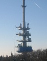
Sometimes
I am also using repeaters. Repeaters are typically placed
on hills or other elevated sites. They are receiving
a signal and retransmit it. They help to extend the
range between stations and thus stations which cannot
hear each other directly can make contact. You can find
tables of repeaters in range of my homes on the respective
pages. Repeaters support not only analog (FM) voice
communication but some of them are supporting also digital
(DStar, DMR) voice transmissions. An increasing number
of repeaters can be linked together and thus the range
of operation can be further increased. The Ham Radio
community operates a backbone network in the 5.6-5.8
GHz range called HamNet. Click on the little map to
the right to get more information. |
|
Many
people think, that Radio Amateurs use only short wave
(HF) frequencies. I guess this is based on the historical
use of Amateur Radio as a low cost medium to talk to
friends all over the world as well as an efficient wireless
system for emergency cases. Not very long time ago private
world-wide communication based on long distance phone
calls was quite expensive. Today people can use a simple
Internet connection to talk to friends all over the
world almost free of charge. However I think that it
is still fascinating to use the HF bands with their
specific propagation characteristics. I am not very
active on the shortwave bands but if you are interested
I will be happy to arrange a sked. |
|
|
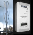
If
you do not have access to a shortwave receiver or suitable
antenna you can also use receivers which are made available
via the Internet. For example the University of Twente
together with the Dutch Amateur Radio Club VERON has
setup a software defined radio and appropriate antenna
in Enschede and makes it publicly available. It is developed
and managed by PA3FWM. This multi-mode receiver covers
8 bands from 65 kHz up to 21.5 MHz and can be operated
by multiple users simultaneously. You only need an Internet-PC
with a soundcard running a web-browser supporting Java
. Click on the picture to the left to get to the respective
page and give it a try. |
Software
defined radio has become a very interesting technology
and is meanwhile also affordable for most radio amateurs.
I have various different SDRs not only for HF reception
but also up to SHF. Some of them I use as a spectrum
scope and demodulator connected to the 10.7 MHz IF output
of my wideband receiver. In the "Sounds from Space"
section of this homepage you can find many audio recordings
complemented by spectrum and waterfall diagrams generated
using SDRs. |

|
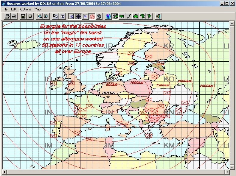
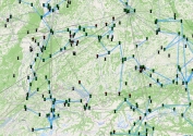
 When
using the 4 element Yagi (actually it is an extended
HB9CV antenna) on 50 MHz very nice contacts are possible.
The 6m band is sometimes called the "magic band"
because all of a sudden very strong signals from stations
far away come up and disappear just as fast shortly
later. Clicking on the little map on the right you can
see a larger map, which will show you an example how
many contacts and countries can be worked during one
afternoon with reasonable good conditions on 6m (example
data are from June 27th 2004). Actually my contact bridging
the longest distance (>6000km) during that day is
not shown, because it was outside of Europe: it was
a contact (QSO) with W1FC located at the East coast
of the USA. When
using the 4 element Yagi (actually it is an extended
HB9CV antenna) on 50 MHz very nice contacts are possible.
The 6m band is sometimes called the "magic band"
because all of a sudden very strong signals from stations
far away come up and disappear just as fast shortly
later. Clicking on the little map on the right you can
see a larger map, which will show you an example how
many contacts and countries can be worked during one
afternoon with reasonable good conditions on 6m (example
data are from June 27th 2004). Actually my contact bridging
the longest distance (>6000km) during that day is
not shown, because it was outside of Europe: it was
a contact (QSO) with W1FC located at the East coast
of the USA.
|
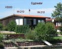
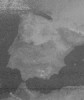
 One of my homes is based in a small
village in a valley, which is surrounded by hills in
most directions. You can see more details of the terrain
if you click on the 3D picture to the left (north is
up). Unfortunately those hills block my transmissions
at low elevation angles and thus I am handicapped with
respect to terrestrial communication at very high frequencies
(UHF and SHF). This is one of the reasons why I became
very fond of satellite operation using the various OSCAR
(orbiting satellite carrying amateur radio) and RS (russian
satellites) satellites. These satellites which are built
by radio amateurs around the world support multiple
operating modes such as voice (SSB, FM), morse code
(CW), data transmissions (packet radio), still pictures
(FAX) and slow scan television pictures (SSTV). One of my homes is based in a small
village in a valley, which is surrounded by hills in
most directions. You can see more details of the terrain
if you click on the 3D picture to the left (north is
up). Unfortunately those hills block my transmissions
at low elevation angles and thus I am handicapped with
respect to terrestrial communication at very high frequencies
(UHF and SHF). This is one of the reasons why I became
very fond of satellite operation using the various OSCAR
(orbiting satellite carrying amateur radio) and RS (russian
satellites) satellites. These satellites which are built
by radio amateurs around the world support multiple
operating modes such as voice (SSB, FM), morse code
(CW), data transmissions (packet radio), still pictures
(FAX) and slow scan television pictures (SSTV).
|
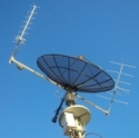
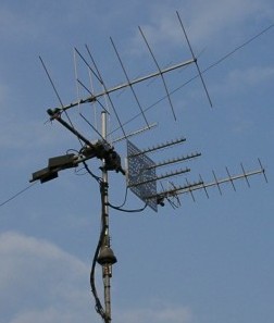
 Satellite communication is challenging because
many parameters of the ground station have to be controlled
carefully and simultaneously. The signals of the low
earth orbiting satellites (LEOs) can be very strong,
such that communication even by a hand held portable
transceiver using an omni-directional antenna is possible.
However some of the satellites have a highly elliptical
orbit and in apogee the satellite is approximately 40000
km away and thus the signals can be also very weak.
Therefore directional antennas and low noise receivers
have to be used. For me it is one of the rewarding areas
to build and optimize the ground station. On the right
picture please see my antenna system which I used to
have for satellite operation. It is presently taken
down for renovation of the room but planned to be put
up again in the near future. On this photography you
see (from left to right) a 2m X-Quad antenna, a 13cm
helical antenna, a 23cm helical antenna array and a
70cm X-Quad antenna. The antenna system can be rotated
both, in azimuth and elevation, manually or fully automated
by a satellite tracking program running on a Windows
PC. Satellite communication is challenging because
many parameters of the ground station have to be controlled
carefully and simultaneously. The signals of the low
earth orbiting satellites (LEOs) can be very strong,
such that communication even by a hand held portable
transceiver using an omni-directional antenna is possible.
However some of the satellites have a highly elliptical
orbit and in apogee the satellite is approximately 40000
km away and thus the signals can be also very weak.
Therefore directional antennas and low noise receivers
have to be used. For me it is one of the rewarding areas
to build and optimize the ground station. On the right
picture please see my antenna system which I used to
have for satellite operation. It is presently taken
down for renovation of the room but planned to be put
up again in the near future. On this photography you
see (from left to right) a 2m X-Quad antenna, a 13cm
helical antenna, a 23cm helical antenna array and a
70cm X-Quad antenna. The antenna system can be rotated
both, in azimuth and elevation, manually or fully automated
by a satellite tracking program running on a Windows
PC.
|
|
|
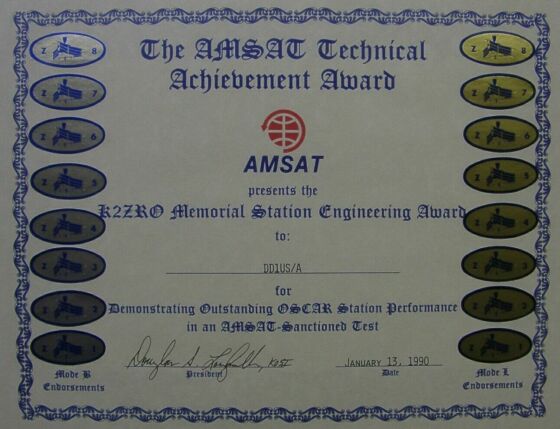
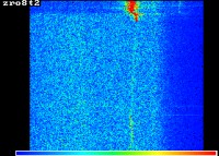
To
be able to appraise the receive system sensitivity of
a satellite ground station, regularly test signals with
well defined power levels (in memoriam to K2ZRO called
ZRO tests) used to be transmitted by the control stations.
The first ZRO test was conducted via AO-10
on May 5th 1985 at 11:30 UTC
in Mode B (145.850 MHz downlink). During
these tests Morse code was transmitted via the satellite
transponder and the uplink signal of was attenuated
precisely in 3 dB steps until the signal was very weak
(level 9 means 27dB below the regular level of the satellites
beacon). I spent some time to optimize my station and
was finally able to receive down to level 8 using rather
small antennas (the 2m and 70cm X-Quad antennas you
can see on the picture above). |
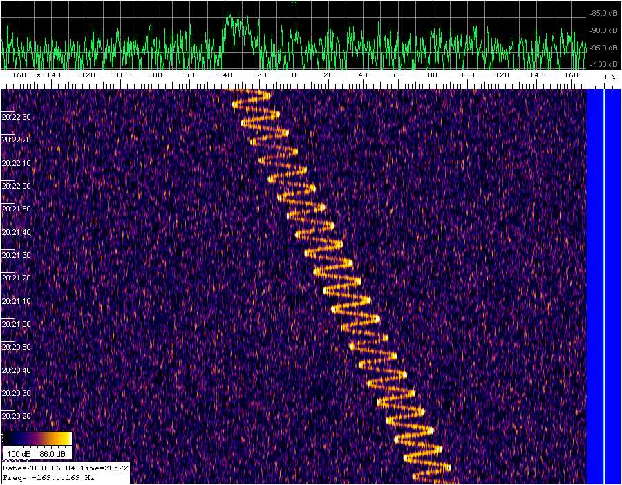
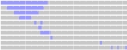
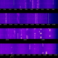
On
AO-10 and AO-13 ZRO transmisions were conducted both,
2m (145 MHz) and 70cm (435 MHz) band. If you would like
to listen to such a ZRO transmission you can click on
the picture to the right. This image is a visualization
of the audio signal with frequency increasing from left-to-right
and time bottom-to-top. You will hear the ZRO transmission
from Andy McAllister conducted on 2m band on April 24th
1993. The sound track is 6 minutes long and contains
continuous data, starting with ZRO level 8 (CW signal
24dB below the beacon) including level 9 (-27dB) and
level A (-30dB) signal, finishing with the "End
of Test" message at full power. Many thanks to
Darrel AA7FV for this record. |

|
|
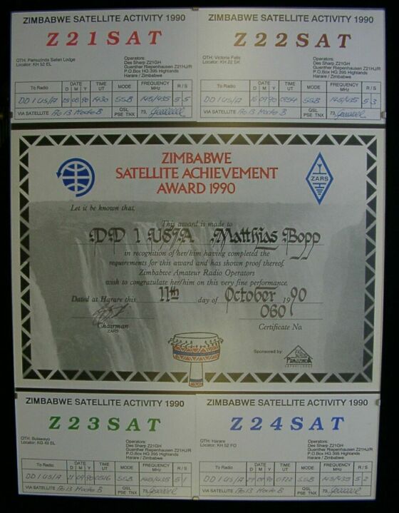
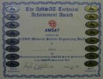
Another
aspect of the ham radio hobby can be to try to reach
as many stations in other countries or continents as
possible. One can apply for various diplomas confirming
the achievement of certain criteria. Furthermore there
are regular competitions called contests, when individual
ham radio operators or whole groups try to make as many
contracts to stations as far away as possible in a given
time.
While I am not very fond of diplomas and contests
I applied for one which is shown on the left. A friend
in Zimbabwe arranged it while travelling to different
locations and operating via AMSAT OSCAR 13. |
The
present location and status of all Amateur radio satellites
can be found on the Homepage of AMSAT Argentina. Please
click on the picture on the right to see this excellent
summary in English language. |
|
|
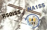
A
table with a summary of recent satellite reception records
is provided by AMSAT NA. Please click on the icon on
the left to access this page. If you receive satellites
yourself please also submit your report on this page,
thanks ! |
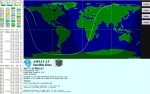
N2YO
provides a web based satellite tracking tool which calculates
the present locations of various satellites and includes
a nice graphical display. If you click on the picture
on the right you can access his program online and get
real time data based on always up-to-date Keplerian
elements. |

|
|
Sometime
I also operate an APRS satellite internet gateway. My
gateway feeds digital signals, which are received on
VHF (145.825 MHz) from various satellites (including
NO-44, NO-60, NO-61 and also from the ARISS experiment
on the international space-station ISS) live to the
internet. This enables the control stations and other
interested people to monitor the traffic and the telemetry
of the satellites while they have no direct access to
the satellites as they are above other parts of the
globe. The more gateways are operated, the better the
coverage. You can access the worldwide collected data
by clicking on the picture to the left. It is also possible
to use the uplink of the satellites to communicate online
with other Ham Radio operators. |
The
various AMSAT groups worldwide are continuously looking
for support for their next generation programs. This
can be actual support in building satellites or components
or a financial support of the projects. |
|
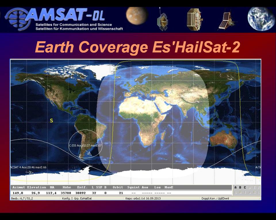
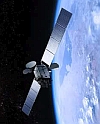
One of the latest successful
projects is P4A (Phase-4-A) or QO-100. This is the first
geostationary satellite for Radio Amateurs. It was sponsored
by Qatar and specified by AMSAT-DL. QO-100 is hosted
on the telecommunications satellite Es'Hail-2 and includes
a narrowband (500kHz wide) and wideband (8.5 MHz wide)
transponder and provides 24/7 coverage of almost half
the surface of the Earth, from Brasil all over Europe
and Africa to Thailand and Artic to Antartica. |
|
I
had various contacts to the cosmonauts and astronauts
in the space stations MIR, the US Space Shuttles and
the International Space Station ISS. Below please find
some examples. An extensive collection with historical
sound tracks related to Satellites, Space Ships and
Space Stations is available in the "Sounds from Space" section of this website. |

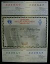
|
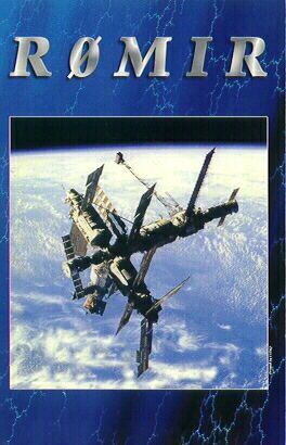
Following
a contact (QSO), ham radio amateurs exchange (QSL) cards
for the confirmation. On the left you can see such a
card which I received from the space station MIR. On
the right you can see my own QSL card. |

|
. |
During
the "Euromir 94" mission in October 1994 Dr.
Ulf Merbold, DB1KM, stayed 4 weeks onboard the space
station MIR. I had the chance to talk to him on 2m.
He used the callsign DP3MIR. You can listen to part
of our contact if you click on the button at the left. |
During
the "Euromir 95" mission Dr. Thomas Reiter,
DF4TR, stayed 6 months onboard the space station MIR.
During this time he was also active in Amateur Radio
using the callsign DP0MIR. I had 4 voice contacts with
Thomas using FM simplex mode in the 2m band (frequency
145,975MHz). The first audio file was recorded on October
4th 1995 around 6 am UTC. The second
file was recorded during another contact some days later. |
|
|
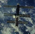
In
1997 the SAFEX Ham Radio equipment onboard the MIR space
station was configured as a 70cm voice repeater. You
can listen to a contact I had with Torsten DG7RO operating
at the club station DL0TZ if you click on the button
at the left. |
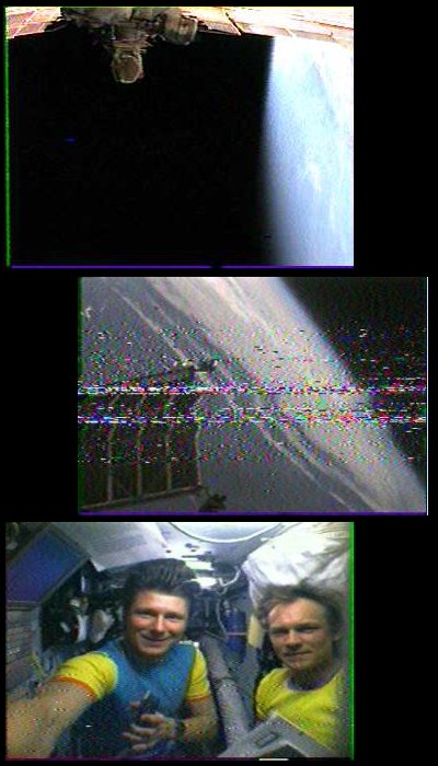
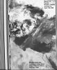
Starting
December 12th 1998 an Amateur Radio SSTV transmitter
was activated in the Russian Space Station MIR. Here
is an article describing how this came into existence.
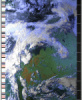
If you like, you may have a look at some pictures I
received directly from the MIR space station in December
1998. The transmission was Slow Scan Television (SSTV,
sub mode Robot). During the first two pictures the camera
was directed out of the window showing part of the space
station. The 3rd picture shows the crew operating the
HAM radio equipment. |

|
|
The
International Space Station (ISS) does also have ham
radio equipment onboard. In October 2002 I had my first
voice contact with Expedition 5 mission commander Valery
G. Korzun. On the right you see Valery using the amateur
radio equipment in the functional cargo block (FCB)
of the ISS. You can find many more reports and recordings
of MIR and ISS contacts in the Sounds from Space section
of this website. |
|

|
Since March
2014 there is also a DATV (Digital Amateur Television)
transmitter in the European Columbus module available.
The transmitter is normally only transmitting a black
video signal unless a camera is attached (mostly for
school contacts). The DATV transmission is on 2395 MHz
in DVB-S2 at 2 Msps. Parameters used are SR=2000, FEC=1/2,
PIDVideo=256, PIDAudio=257, MPEG2. Since January 2018
I am part of the ground station network which receives
the signal and streams it via the internet to a central
server in UK where it is combined and made available
for all interested people (see the link to the right). |

|
|
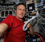
On May 28th
2014 German astronaut Alexander
Gerst KF5ONO
started his first mission named "blue
dot" to the ISS which lasted until he landed safely
on November 10th 2014.
During his second mission called "horizons"
on the ISS, starting on June 6th 2018
and lasting until December 20th
2018, he became also the first German commander of the
ISS.
During his second stay on the ISS I was involved
in arranging and conducting 3 school contacts.
If you click on the picture to the left you get to a
page where you learn more and listen to the school contacts
which he conducted. |


|
|
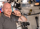
On November
11th 2021
German ESA Astronaut Matthias Maurer KI5KFH arrived
at the ISS to conduct his first mission called "Cosmic
Kiss". As part of his mission he is also conducting
ARISS school contacts using the Amateur Radio station
in the Columbus module of the ISS. He is using the callsign
DP0ISS. In February 2022 a school contact with 2 schools
in the Breisgau area in Germany are scheduled which
I am arranging together with other radio amateurs. If
you click on the picture to the left you get to a page
where you learn more and listen to the school contacts
which he already conducted. If you click to the picture
right of this text you can read more about our preparations
of the school contact. |

|
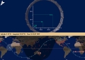
If you are interested, where the
international space station ISS is presently located
and whether you may be able to listen to its transmissions
or watch it in the twilight, the picture to the right
shows you its current location. If ISS is active in
Ham radio while over Europe the normal frequencies to
be used are 145.825 MHz for Packet Radio / APRS (up
and downlink) or 145.800 MHz (with 145.200 MHz for the
uplink) for voice contacts. Please remember that there
will be some Doppler shift of up to +/- 5Khz while ISS
passes over you. You will have to tune your receiver
to a higher frequency while ISS approaches you and to
a lower frequency when it moves away. In reverse you
will have to tune your transmitter for the uplink. |

(courtesy
of ESA&Heavens-Above)
|
|
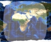
In
addition the link below will get you to a simulated
real time view of the Earth, as if watched through the
round window of the US Destiny Lab on ISS. Please note
that quite often you will only see the blue ocean as
Earth is mostly covered by water. |
|
|
You
probably already noticed based on the descriptions above
that I am very interested in Space Communications overall.
Therefore I decided to add a section with historical
sound tracks related to Satellites, Space Ships and
Space Stations. I hope you will enjoy browsing it. Please
click on the picture on the left to access these pages
which I named "Sounds from Space". |
|
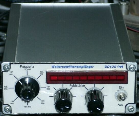
 Another very interesting
mode is Faxsimile (FAX). Here, besides ham radio operation,
also the reception of polar orbiting weather satellites
(LEOs) is possible. I built the necessary FM receiver
(shown on the left side). With this receiver and my
2m X-Quad antenna I did receive the automatic picture
transmissions (APT) of the NOAA and Meteor weather satellites
at 137 MHz and decoded it with the sound card of my
PC. The complete station was running fully automated
and is controlled by a PC. Presently the X-Quad antennas
are down and I am using omni-directional antennas like
turnstiles and QFHs. Receivers include the R2FX from
Holger Eckardt DF2FQ, the Vierling Weatherman, the wide-band
receiver ICOM PCR-100 and the Airspy SDR. Another very interesting
mode is Faxsimile (FAX). Here, besides ham radio operation,
also the reception of polar orbiting weather satellites
(LEOs) is possible. I built the necessary FM receiver
(shown on the left side). With this receiver and my
2m X-Quad antenna I did receive the automatic picture
transmissions (APT) of the NOAA and Meteor weather satellites
at 137 MHz and decoded it with the sound card of my
PC. The complete station was running fully automated
and is controlled by a PC. Presently the X-Quad antennas
are down and I am using omni-directional antennas like
turnstiles and QFHs. Receivers include the R2FX from
Holger Eckardt DF2FQ, the Vierling Weatherman, the wide-band
receiver ICOM PCR-100 and the Airspy SDR.
 You can find the latest status about
which WX-Sats are active and the respective frequencies
when clicking on the icons on the right. You can find the latest status about
which WX-Sats are active and the respective frequencies
when clicking on the icons on the right.
|
|
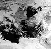
If
you click on the icons below you can see some of the
weather satellite APT pictures which I received. Behind
most of the icons you will actually find a collection
of pictures. |

METEOR 2-1
|

METEOR 2-2
|

METEOR 3-4
|
METEOR 3-5
|

NOAA 9
|
NOAA 10
|
NOAA 11
|
NOAA 12
|
NOAA 14
|
NOAA 15
|

NOAA 18
|

NOAA 19
|
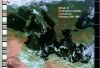
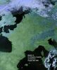
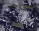
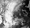
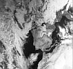
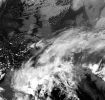
If you want to know how such an APT
transmission from a Meteor or a NOAA satellite sounds,
please click on the receiver icons below. You can also
learn more about such transmissions on my page "Sounds from Space". |
|
Russian
METEOR
weather
satellites |

|
|
US
NOAA
weather
satellites |

|
|
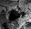
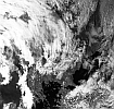
In
January 2015 I started to receive also LRPT (low rate
picture transmissions) from Meteor M-N2 who was launched
in July 2014. This satellites transmits also in the
VHF band but uses digital modulation (QPSK). I am using
the same QFH antenna as I use it for APT picture reception
but an AOR AR-5000 wideband receiver with an SDR (software
defined receiver) attached to the 10.7 MHz output of
the AR-5000.
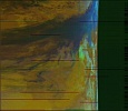
METEOR M-N1
|
METEOR M-N2 |
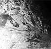
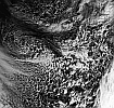
In October 2017 I started to receive
also the HRPT weather pictures of various satellites
including NOAA-15, NOAA-18, NOAA-19, Meteor M-N2, METOP-A,
METOP-B, Fengyun 3A, Fengyun 3B and FENGYUN 3C. I am
using a 2.3m fine-mesh dish with automated tracking.
The receiver is an Airspy-Mini SDR. I am using WXTrack
for providing the tracking data of the satellites by
DDE, PSTRotator using the DDE-data to control the rotator
and XHRPT to demodulate the signal. The I/Q data from
the Airspy-Mini is streamed via IP to XHRPT by SpyServer
which is running on an OdroidXU4 board. |
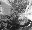
NOAA-15 HRPT
|
NOAA-18 HRPT
|
NOAA-19 HRPT
|
METOP-A AHRPT
|
METOP-B AHRPT
|
METEOR M-N2 HRPT
|
FENGYUN 3A HRPT
|
FENGYUN 3B HRPT
|
FENGYUN 3C HRPT
|
|